Composite structures are more and more utilized in different branches of industry. Nowadays structures are made from various fibre reinforced polymer (FRP) composite materials. Thus, the up-to-date non-destructive testing (NDT) techniques should handle with the wide range of these materials and potential defect types that could occur in such materials. Typical damage in composite are matrix cracking and delamination caused by impact[1, 2] but attention should also be focused on such problems like the performance of structural bonds, moisture content or thermal degradation.
There are many NDT techniques that can be utilized for damage detection and localization in FRP materials. Several NDT techniques like ultrasound testing(UT)[1], active infrared thermography[2], eddy currents[3], X-ray tomography[4], terahertz spectroscopy[1, 5]and guided waves based[6]have been utilized in the literature. In addition to damage detection, another important problem that needs to be addressed is the detection of reduced mechanical performance of bonded joints in composite materials. For this purpose, research is conducted towards development of extended NDT (ENDT) methods[7].
The mechanical performance of adhesive bonds in composite structures depends strictly on the properties of the surfaces to be joined. Improper preparation of the adherents may lead to creation of weak bond that are not able to carry the desired load. Therefore, a reliable tool is crucial to characterize and assure the quality of the surface prepared for bonding as well as bonded joints.
One such promising ENDT method for surface assessment is the technique based on electronic nose[8]. Beside the problem of surface assessment, the important task is to assess the structural performance of composite bonded structures. The example of these techniques are electromechanical impedance[9]and laser-induced shock waves[10].
Another popular methods that assess the state of the structure in real time are called structural health monitoring (SHM). In this approach a network of transducers (actuators and/or sensors) permanently installed on investigated structure is utilized. The aim of the network is to excite and sense diagnostic signals (active system) or only to listen to signals by the sensors (passive system). Ref.[11] utilized sensor network of piezoelectric transducers for impact detection, and employed Bayesian updating and Kalman filter in order to isolate the influence of changing operational condition. Passive SHM systems are also based on fibre Bragg grating (FBG) strain sensors. Ref.[12] utilized FBG sensors for strain sensing in wire steel strand structure. Results of numerical research related to active SHM system for detection of corrosion in pipes were presented in Ref.[13]. Ref.[14] presented experimental results related to active structural assessment system for pipes, and investigated cases with different fluids transported through the pipe.
Guided wave propagation method can be used in SHM when piezoelectric transducers are utilized for elastic wave generation and sensing purposes. This method could be used also as NDT technique when non-contact measurements are conducted using laser scanning vibrometer and the guided wave excitation is realized using piezoelectric transducer.
In this paper, we utilize NDT approach based on analysis of full wavefield registered by scanning laser doppler vibrometry (SLDV). We focus on interactions of elastic waves with discontinuities in the form of simulated delamination (teflon insert) and impact on delamination. We also emphasize guided wave mode conversion S0/A0' that occurs at the discontinuity location.
Full wavefield measurement approach based on SLDV allows visualization and analysis of guided wave propagation in complex structures. Beside this, detailed analysis of GW propagation in frequency-wavenumber domain for the damage detection can be performed[6]. Refs.[15, 16] proposed damage detection approach based on local wavenumber analysis. Ref.[17] proposed application of scanning spatial-wave number filter for damage detection in composite aerospace structure. In this case, instead of full wavefield approach, point-wise measurement approach solely based on piezoelectric transducers was proposed. Ref.[18] investigated problem of damage detection in composite aerospace structures. The authors proposed damage detection algorithm based on Gaussian mixture model-based path-synthesis accumulation imaging which was tested under the temperature variation. Ref.[19] proposed problem of barely visible impact damage detection based on evaluating changes in group velocity and amplitude (wave attenuation). Ref.[17] utilized spatial-wave number filter for online characterization of multi-impact in aircraft composite structures. Refs.[16, 20] investigatedproblem of delamination localization using full wavefield approach. Refs.[21-23] focused on wave trapping effect in the delaminated region. SLDV technique was also utilized for analysis of mode conversion phenomenon[24]. This phenomenon was also investigated in composite structures where S0/A0' mode conversion due to interaction of S0 mode with delamination was observed[25]. Ref.[25] also presented numerical results based on spectral element method (SEM). Simulations of guided wave propagation that take into account problem of mode conversion were also conducted by Ref.[26] using conventional finite element method (FEM). This phenomenon was also investigated in composite structures where S0/A0' mode conversion due to interaction of S0 mode with delamination was observed[25]. Ref.[27] also utilized mode conversion phenomenon for damage detection, and employed 3D full wavefield measurements based on scanning laser vibrometer with mode conversion effect as an indicator of damage.
In this paper, we investigated interactions of elastic guided waves with simulated delaminations (teflon inserts) and impact damage. We also present results of application of auxiliary NDT method based on THz spectroscopy. The aim of application of THz spectroscopy is to indicate depth where discontinuity locates, and to prove the presence of delamination.
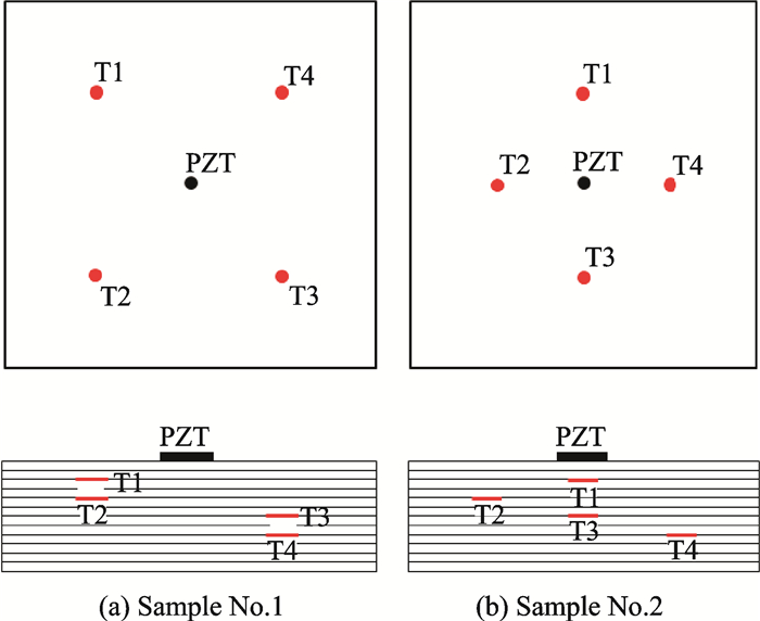
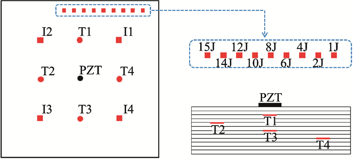
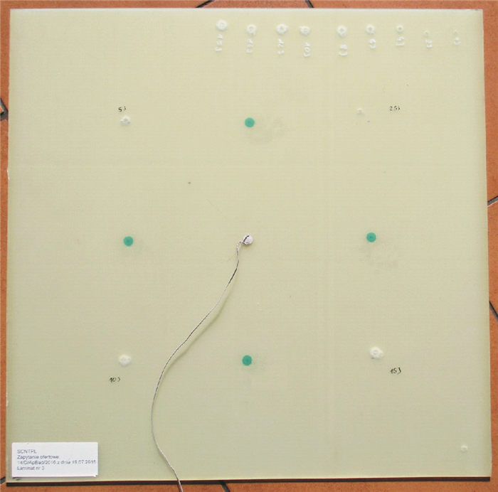
1 Measurement Set-upExperimental research was related to GFRP samples in the form of panels with dimensions 500 mm × 500 mm and thickness 1.5 mm. Each panel consisted of twelve layers of VV192T/202 IMP503 prepregs with orientations: [0/90/0/90/0/90]S. At the manufacturing stage of each sample, teflon inserts were located between different layers of prepreg. In sample No.1, four circular teflon inserts T1—T4 (each with a diameter of 20 mm) were located at different depths and angles 45°/-45°(Fig. 1(a)). In sample No.2, four circular teflon inserts T1—T4 (each with diameter 20 mm) were located at different depths and angles 0°/90°(Fig. 1(b)). In sample No.3, four circular teflon inserts T1—T4 (each with a diameter of 10 mm) were located same as those in sample No.2. However, after manufacturing sample No.3, different cases of impact damage were in duced additionally. In the first step, four impacts,denoted as I1—I4 (Fig. 2), at different locations and with different energies were made. Impact energies I1—I4 were equal to 2.5, 5, 10 and 15 J. In the next step, nine additional impacts were made near the top edge of the plate (Fig. 2). In this case, impacts had different energies ranging from 1 J up to 15 J (Fig. 2). View of sample No.3 is presented in Fig. 3.
|
Fig. 1 GFRP samples with different teflon insert locations(a 20 mm diamater inserted) |
|
Fig. 2 GFRP sample No.3 with teflon inserts and impact damage(a 10 mmdiamater inserted) |
|
Fig. 3 View of GFRP of or sample No. style="class:table_bottom_border" |
Guided waves were excited by piezoelectric transducer located in the middle of each sample, on top sample surface (Figs. 1—3).
Guided wave sensing process was conducted in non-contact manner using 3D Polytec PSV-400 scanning laser vibrometer. Measurements were taken at the bottom surface of each sample which was covered additionally by retro reflective foil, in order to enhance laser reflection. This allowed reduction of the number of signals which would be taken for averaging. Only one scanning laser head of scanning laser vibrometer was utilized (measurements were taken along laser beam approximating out-of-plane guided elastic wave velocities). Measurements were performed for dense mesh of points spanned over the area of investigated samples.
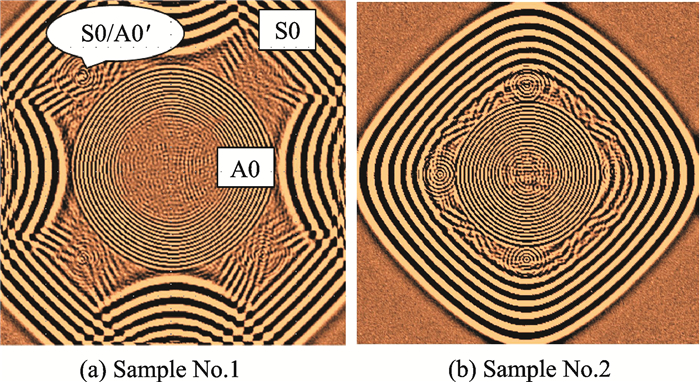
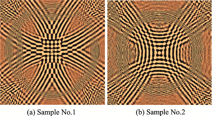
2 Results for Full Wavefield AnalysisFig. 4(a) shows the selected frame from animation of guided wave propagation in GFRP sample No.1. In this sample, circular teflon inserts with diameters of 20 mm were located in the manner presented in Fig. 1(a). In this case, excitation frequency was 200 kHz (tone burst excitation, 5 cycles of sine modulated by Hann window). The aim of utilization of tone burst excitation was to concentrate energy in narrow frequency band which allows reduction of elastic wave dispersion effects. In Fig. 4(a), propagation of two fundamental modes, A0 and S0, can be noticed. Modes can be distinguished by their different wavelengths. Mode S0 has longer wavelength and higher velocity of propagation than A0 mode. At the time of frame, as presented in Fig. 4(a), S0 mode reflects from the plate edges. Moreover, in this frame, symmetric S0 mode converts to A0' mode in the locations of teflon inserts T1—T4. A0' denotes antisymmetric mode generated after S0 mode conversion. Intensity of S0/A0' mode conversion could be characterized by amplitude of generated A0' mode. It could be simply noticed that intensity of S0/A0' mode conversion depends on the depth at which teflon insert is located. This intensity is the lowest for insert T4 located deepest in the relation to panel thickness, compare to Fig. 1(a).
|
Fig. 4 S0/A0' mode conversion at teflon inserts in GFRP samples(excitation frequency of 200 kHz) |
Fig. 4(b) shows the selected frame from animation of elastic waves in sample No.2. In this sample, teflon inserts with diameters of 20 mm are located in the manner as presented in Fig. 1(b). In this frame, S0/A0' mode conversion due to interaction of S0 mode with teflon inserts is clearly visible. The amplitude of A0' mode also depends on the depth at which insert is located. Smallest amplitude of converted mode is in the case of teflon insert T4 located near the bottom surface of the sample.
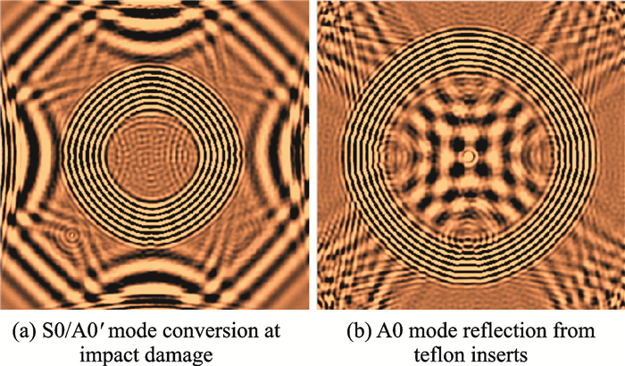
Reflections of A0 mode from the teflon inserts in sample No.1 (Fig. 5(a)) and No.2 (Fig. 5(b)) are clearly visible. Reflections are caused by difference in acoustic impedance of material of panel and inserts.
|
Fig. 5 A0 mode reflections from teflon inserts in samples(excitation frequency of 200 kHz) |
Fig. 6 shows selected frames from animation of waves propagation in sample No.3 with smaller diameter of teflon inserts (10 mm) and impact damage. Locations of all investigated defects were presented in Fig. 2 and Fig. 3. Excitation frequency was 100 kHz. In Fig. 6(a), S0 mode due to interaction with impact damage I3 and I4 (Fig. 2), converts to antisymmetric mode denoted as A0'.
|
Fig. 6 Elastic waves interaction with discontinuities in sample No.3(excitation frequency of 100 kHz) |
When the excitation frequency was 100 kHz, mode conversion effect was not visible in the case of remaining discontinuities in the sample described in previous section (teflon inserts T1-T4 and impacts I1-I2). However, in this case,S0/A0' mode conversion phenomenon was observed additionally on the edges of plate. Characteristic wavelength change could be observed after reflection of S0 mode from the plate edges. A0' mode with shorter wavelength propagates just after S0 edge reflected mode (Fig. 6(a)). This was caused by slight thickness change just near the plate edges(defects from manufacturing process). Mode conversion always occurs for non-symmetric discontinuities in respect to the wave-guide thickness [25, 28].
In Fig. 6(b), reflections of A0 mode from teflon inserts T1—T4 (see Fig. 2) can be seen. This was caused by different acoustic impedance of material of GFRP panel and material of insert.
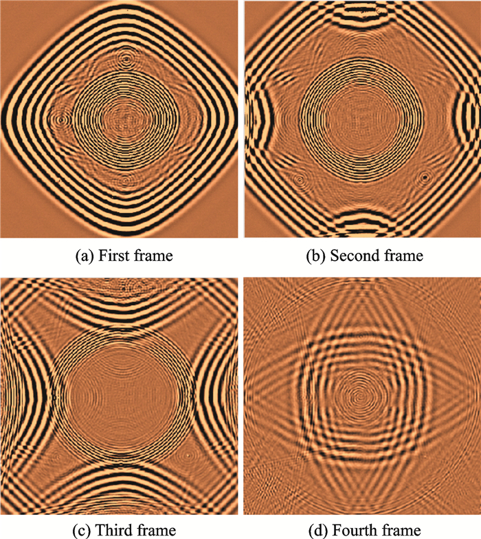
Next, measurements of guided wave propagation in sample No.3 were performed with the excitation frequency of 200 kHz. Results in the form of subsequent frames taken from animation of guided wave propagation were presented in Fig. 7. Propagation of S0 and A0 modes is clearly visible in Fig. 7. Frame presented in Fig.7(a) was taken at time instant in which S0 mode reached the plate edges and already has propagated through areas with teflon inserts T1-T4. In this frame S0/A0' mode conversion resulted from interaction of S0 mode with teflon inserts can be clearly visible.
|
Fig. 7 Elastic waves interaction with discontinuities in sample No.3(excitation frequency of 200 kHz) |
Interestingly, S0/A0' mode conversion occurs also for teflon insert T3 which is located at the middle of plate thickness, symmetrically in respect to the thickness (Fig. 2). Mode conversion occurs always in the region without symmetry. Existence of damage/discontinuity always destroys the symmetry of sample and results in mode conversion[28].
In Fig. 7(a), teflon insert T3 was located between the sixth and the seventh layer, in the middle of the thickness(symmetry). Besides, mode conversion S0/A0' is still clearly visible. It could be explained by the fact that in real conditions any kind of introduced discontinuity always destroys the symmetry.
In Fig. 7(b), S0 mode reflects from the plate edges. Moreover S0/A0' mode conversion in the areas of impact I3 and I4 is clearly visible.
Effects of mode conversion are also visible in the location of teflon inserts T1 and T2 and barely visible in the case of T3.
Mode conversion can also be clearly noticed on the left edge of the plate. This was caused by change in thickness near the edge of the panel, which was defect from the manufacturing process. In Fig. 7(c) S0/A0' mode conversions on the all plate edges can be noticed. Explanation of this phenomenon was given previously.Moreover mode conversion is visible in the areas of impacts with energies 1 J—15 J, near the top edge of the plate compared with that in Fig. 2. Teflon inserts also caused reflections of A0 mode, which are visible in the same figure. In Fig. 7(d), S0/A0' mode conversion on the piezoelectric transducer placed in the middle of the plate could be also seen. Piezoelectric transducer is breaking the symmetry for the propagating waves and therefore causes mode conversion.
3 Weighted RMS Energy MapsIn this section guided wave signal processing algorithm is presented. Aim of algorithm is to visualize discontinuities location. Algorithm is based on calculation of weighted root mean square (WRMS) indicator for full wavefield measurements of guided wave propagation. As consequence of application of WRMS algorithm, energy distribution related to propagation of elastic waves and its interaction with discontinuities in the structure is obtained. In the WRMS algorithm, weight factor is utilized for the aim of compensation of guided wave damping in the investigated samples.
The WRMS indicator can be calculated as
| $ {\rm{WRMS}} = \sqrt {\frac{1}{N}\sum\limits_{k = 1}^N {{w_k}{s^2}} } $ | (1) |
where k is the sample number and the weighting factor wk is defined as
| $ {w_k} = {k^m}\;\;\;m \ge 0 $ | (2) |
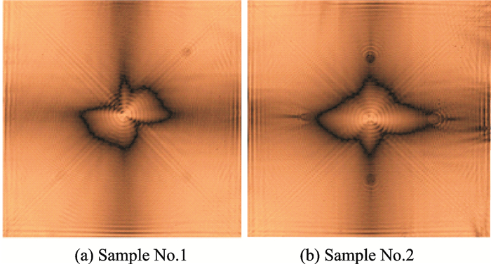
In Fig. 8(a) WRMS energy map for guided wave propagation in sample No.1, with coefficient m=0.65 and the excitation frequency 200 kHz is presented. In this map, location of point where guided waves were excited in the middle with the largest energy concentration is visible.
|
Fig. 8 WRMS energy map (excitation frequency of 200 kHz and m=0.65) |
Moreover, locations of teflon inserts T1—T3 are clearly visible. Location of insert T4 is not visible. Besides, circular shape of inserts could be also noticed. In Fig. 8(b), such a map for sample No.2 is presented. In this case, locations of all teflon inserts T1—T4 are clearly visible. Fig. 8 shows that sensitivity of damage assessment algorithm for teflon inserts located at angles 0°/90° is higher than for inserts located at angles 45°/-45°. This is caused by orientation of reinforcing fibres. In all the samples, reinforcing fibres are located at angles 0°/90°. Energy of waves is mainly distributed along these directions what is clearly seen in Fig. 8. This effect was also noticed and discussed in Refs.[24, 25].
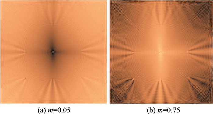
Fig. 9 presents WRMS energy maps for guided wave propagation with an excitation frequency of 100 kHz. Fig. 9(a), shows WRMS map with m=0.05. Locations of teflon inserts T1—T4 and impact damage I3 and I4 are clearly visible in the areas where the change of energy distribution occurs. This map does not indicate location of impacts I1 and I2 as well as impacts near the top edge of plate. Fig. 9(b) shows WRMS energy map with the coefficient m=0.75. In this case, stronger changes in guided wave energy distribution in locations of teflon inserts T1—T4 and impact damage I3—I4 are visible. However, energy map does not indicate locations of impacts I1 and I2 as well as impact near the edge.
|
Fig. 9 WRMS energy map for sample no.3(excitation)frequency 100 kHz |
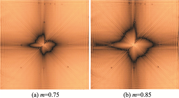
Fig. 10(a) shows WRMS energy map with the coefficient m=0.75. Point of guided wave generation (in the middle) with the largest energy concentration is visible. Moreover, locations of four teflon inserts T1—T4 as well as impacts I3 and I4 are clearly visible. Intensity of elastic wave energy due to interaction of waves with teflon inserts depends on its location in respect to the depth of plate. Similar effects were observed in Ref.[25].Beside, locations of impact damage, located near the top edges, are visible.
|
Fig. 10 WRMS energy map for sample No.3 with excitation frequency of 100 kHz |
Five locations of impacts with energies 15, 14, 12, 10, 8 J (counting from the left to the right in Fig. 2) located near the top edge of plate can be distinguished (Fig. 3).
Fig. 10(b) presents WRMS energy map with the coefficient m=0.85. Slight change of value of coefficient m improved indications of location of mentioned discontinuities. This coefficient could be used for the control of the contrast of the energy map. Its value should be selected by the trial error method in such a way to obtain good contrast of damage and referential part of the sample. It should be noticed that in this area, S0/A0' mode conversion on piezoelectric transducer occurs. This effect can also influence distribution of guided wave energy.
4 Terahertz SpectroscopyIn this section, results from terahertz spectroscopy are presented. Measurements were conducted using Teraview TPS Spectra 3000 spectrometer which generates impulses of electromagnetic wave in frequency range from 0.1 up to 3 THz. Impulses were sent repeatedly and interacted with the structure of GFRP sample and discontinuities inside it (teflon inserts and impact damage). This non-contact measurement system allows us to perform measurements in reflection and transmission modes. Results presented in this paper were based on reflection measurements only. Reflection mode is more feasible for analyzing real structures where access to the structure is very often limited to only one side.
THz spectroscopy is based on analysis of propagation of electromagnetic waves in the terahertz frequency band. In THz spectroscopy, differences of values of real part of refractive indexes n of interfaces of material and defect are very important. Electromagnetic wave propagating in the material is reflected from interfaces with different values of refractive indexes n. Imaginary part of refractive index is related to electromagnetic wave attenuation.
THz spectroscopy method can be utilized for damage assessment in the dielectric materials, like GFRP investigated here. Application of THz technique for detection of delamination can be found Refs.[1, 5].THz spectroscopy could also be utilized in order to detect and locate the moisture content in GFRP samples[29]. Besides, Ref.[30] utilized this method for detecting illicit drugs in mail. THz spectroscopy could be also utilized for detcting explosive materials[31, 32]. Ref.[33] utilized THZ spectroscopy for quality control and counterfeit detection in electronic components.
As result of the THz spectroscopy, three types of data are obtained: Single signal at one point (A-scan), set of signals along a line (B-scan) and set of signals in certain area (C-scan). B-scan allows investigation of the material structure in vertical cross-section, e.g., location of defect along the thickness, determination of defect thickness and length. C-scan shows the horizontal cross-section of material at certain depth, e.g., planar location of defects, its length and width, shape of defect.
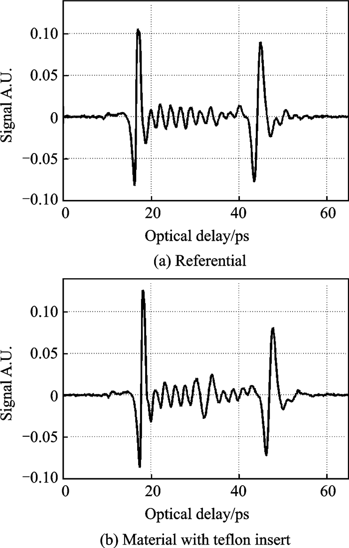
Fig. 11 shows example of THz signals called A-scans. Signal in Fig. 11(a) was taken from the referential area of sample No.3 without any defect. Two strong reflections of electromagnetic wave can be distinguished From the top surface of the sample (interface air/GFRP) at time 18 ps, and from the bottom surface of sample (interface GFRP/air) at 42 ps. Small reflections visible between two large peaks are related to reflection of THz wave at interfaces of composite layers. Signal in the Fig. 11(b) was taken from area of sample No.3 including teflon insert. Beside the two reflections from top and bottom surface of the sample, additional reflection from the teflon insert can be noticed at 30 ps. This reflection was caused by different values of real parts of refractive indexes n for GFRP material and teflon. In the case of GFRP material, real part of refractive index nG=2 [29], while as refractive index for teflon, nT=1.437 [34].
|
Fig. 11 THz signals (A-scans) for GFRP sample |
These differences cause reflections of electromagnetic wave and allow to visualize location of such a material discontinuity.
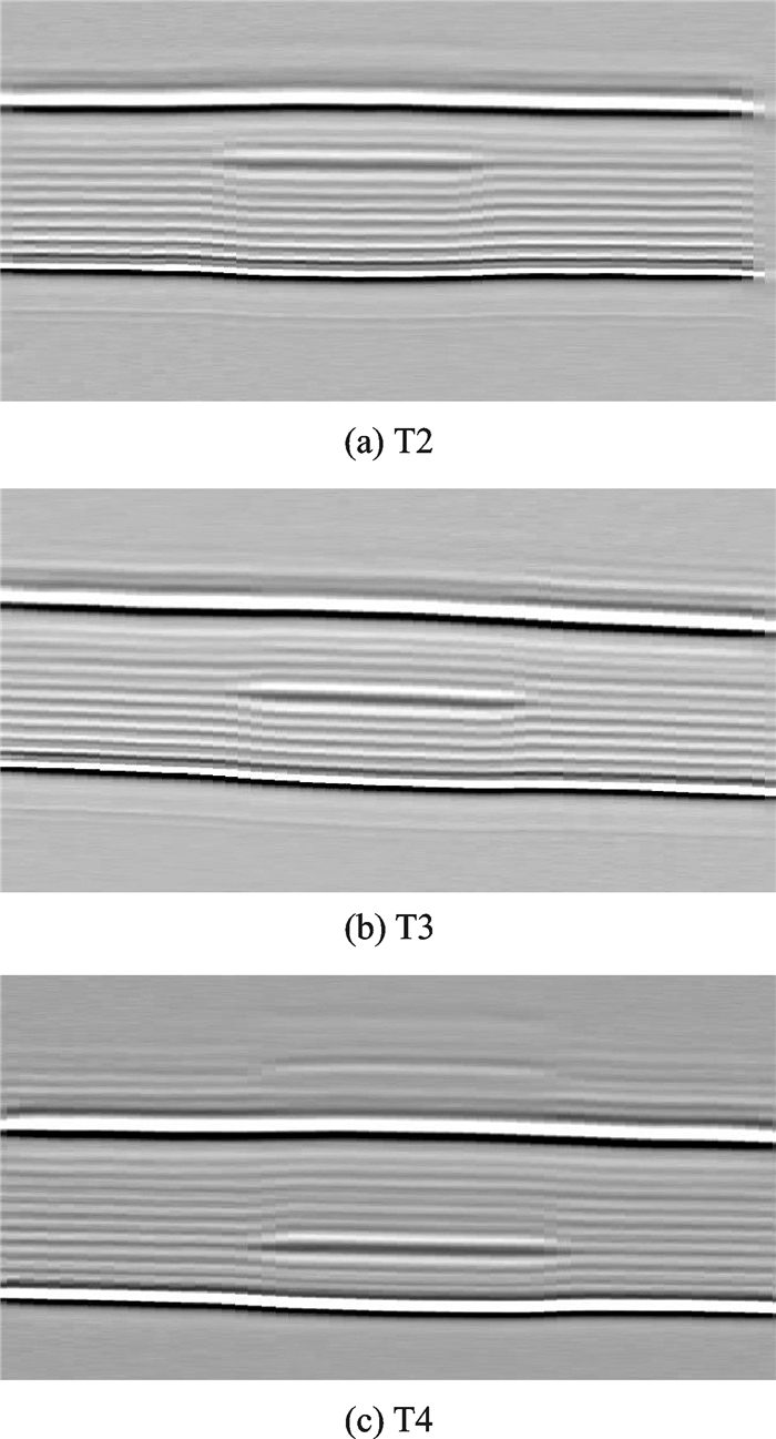
In Figs. 12(a—c) shows B-scans for the areas of sample No.3 around teflon inserts T2, T3 and T4, respectively. Vertical cross-section of the GFRP sample is visible. Clear bottom line is related to the top surface of the sample and reflection of THz wave from it, while as the top line is related to the bottom surface of sample. This large contrast at the edges of panel is related to different refractive indexes of GFRP material and air. Locations of the teflon layer at different depths are also clearly visible. In Fig. 12(b), B-scan was created for teflon insert T3 located in the middle of plate thickness (the same number of composite layer above and below teflon). However, even in this location, it is clearly visible that there is no perfect symmetry in respect to the thickness. This is source of guided wave mode conversion S0/A0' visible in Fig. 7(a) and discussed in section 2. Moreover layered structure of GFRP sample is clearly visible, it is possible to distinguish all layers of the sample.
|
Fig. 12 B-scan for area with teflon inserts |
In Figs. 13(a—c), B-scans for the areas of intact GFRP sample no.3 and areas around impacts I3 and I4 are presented. In the case of intact sample (Fig. 13(a)) the top and bottom surface of sample as well as layered structure are visible.
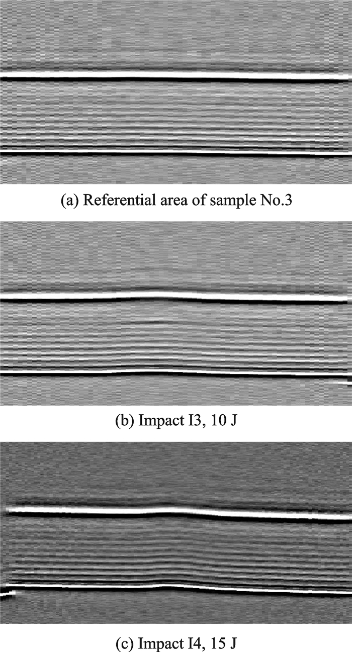
|
Fig. 13 B-scans |
In the case of impact I3 with 10 J, energy difference in certain contrast between layers are visible (almost in the middle of the sample thickness). This contrast could be related to delamination of material. Delaminated region could contain air which could cause change in electromagnetic wave propagation due to differences of refractive indexes of GFRP and it. Moreover, deformation of the top and bottom surface due to impact could be noticed. In the case of impact I4 with 15 J energy, there is no clear contrast visible. It looks like there is no delamination. Only deformation of sample due to the impact force applied is clearly visible.
Results of THz spectroscopy in the form of B-scans showed that impact damage could be a source of delamination or only plastic deformation of sample in the impacted region. In both cases, symmetry of sample is not perfect and this is source of elastic wave mode conversion S0/A0' discussed in section 2.
5 ConclusionsIn this paper, interactions of elastic guided waves with discontinuities in the form of simulated delaminations (teflon inserts) and real impact damage were investigated. Teflon inserts, with diameters of 10 and 20 mm, were located at different depths of composite panels. Different impact energies ranging from 1 J to 15 J were also investigated. Teflon inserts caused S0/A0' mode conversions, even in the case when inserts was located in the middle of the sample thickness. Intensity of S0/A0' mode depends on depth at which inserts are located. Mode conversion S0/A0' was also observed for the impact damage with energies from 8 J to 15 J. Besides, mode conversion was observed near plate edges (thickness change) and at location of piezoelectric transducer. In both cases, as well as for investigated defects (teflon inserts, impact damage), there was no symmetry in respect to the thickness of the waveguide.
Damage localisation algorithm based on WRMS energy of guided waves indicated location of four investigated teflon inserts T1— T4 (a diameter of 20 mm) when they were located at angles 0°/90° the same like orientation of reinforcing fibres. Problem with indication of location of T4 insert (located deepest) and placed at angle 45° occurred. Sensitivity of algorithm for angles 45°/-45° is lower than that for angles 0°/90° (the orientation of reinforcing fibres). Locations of impact damage I3 with energy 10 J and I4 (15 J) for the excitation frequencies 100 kHz and 200 kHz were successfully found. Location of impacts I1 (2.5 J) and I2 (5 J) were not indicated. In the case of excitation frequency 200 kHz, locations of additional impacts near the top plate edge (Figs. 2, 3) for the impact energies 8—15 J were clearly visible. Smallest energy of impact that can be detected by elastic waves was 8 J.Contrast of referential to damage area in the WRMS maps can be controlled by weighting factor m.
Moreover, THz spectroscopy was utilized as auxiliary method to exhibit the real location of teflon inserts and to prove that delamination was created by the impact. Results showed that teflon inserts were located at correct depth according to the manufacturing specification. Moreover, even for teflon insert located in the middle of the plate thickness, there is no ideal symmetry. This fact caused A0/S0' elastic wave mode conversion. Impact force caused mainly plastic deformation of material without separation/delamination of layers. Only in the case of impact I3 (10 J) delamination was detected.
Acknowledgement
The authors would like to gratefully acknowledge financial support given by the Polish National Science Centre(No.UMO-2014/13/D/ST8/03167).
| [1] |
DONG J, KIM B, LOCQUET A, et al. Nondestructive evaluation of forced delamination in glass fiber-reinforced composites by terahertz and ultrasonic waves[J]. Composites Part B, 2015, 79: 667-675. DOI:10.1016/j.compositesb.2015.05.028 |
| [2] |
MEOLA C, BOCCARDI S, CARLOMAGNO G M, et al. Nondestructive evaluation of carbon fibre reinforced composites with infrared thermography and ultrasonic[J]. Composite Structures, 2015, 134: 845-53. DOI:10.1016/j.compstruct.2015.08.119 |
| [3] |
HEUER H, SCHULZE M, POOCH M, et al. Review on quality assurance along the CFRP value chain-Non-destructive testing of fabrics, preforms and CFRP by HF radio wave techniques[J]. Composites Part B:Engineering, 2015, 77: 494-501. DOI:10.1016/j.compositesb.2015.03.022 |
| [4] |
UHRY C, GUILLET F, DUVAUCHELLE P, et al. Optimisation of the process of X-ray tomography applied to the detection of defects in composites materials[C]//Proc of Digital Industrial Radiology and Computed Tomography. Ghent, Belgium: [s. n. ], 2015.
|
| [5] |
DONG J, LOCQUET A, CITRIN D S. Enhanced Terahertz imaging of small forced delamination in woven glass fibre-reinforced composites with wavelet de-noising[J]. Journal of Infrared, Millimeter and Terahertz Waves, 2016, 37: 289-301. DOI:10.1007/s10762-015-0226-9 |
| [6] |
CARRARA M, RUZZENE M. Frequency-wavenumber design of spiral macro fiber composite directional actuators[J]. Spie Smart Structures, 2015, 9435: 94350M-12. |
| [7] |
EHRHART B, VALESKE B, ECAULT R, et al. Extended NDT for the quality assessment of adhesive bonded cfrp structures[C]//International Workshop Smart materials, structures & NDT in aerospace Conference NDT. Canada: [s. n. ], 2011.
|
| [8] |
VITO S D, MIGLIETTA M L, MASSERA E, et al. Electronic noses for composites surface contamination detection in aerospace industry[J]. Sensors, 2017, 17(4): 754. DOI:10.3390/s17040754 |
| [9] |
MALINOWSKI P, OSTACHOWICZ W M, BRUNE K, et al. Study of electromechanical impedance changes caused by modifications of CFRP adhesive bonds[J]. Journal Fatigue and Fracture of Engineering Materials and Structures, 2017, 40(10): 1592-1600. DOI:10.1111/ffe.v40.10 |
| [10] |
ECAULT R, TOUCHARD F, BOUSTIE M, et al. Numerical modelling of laser-induced shock experiments for the development of the adhesion test for bonded composite materials[J]. Composite Structures, 2016, 152: 382-394. DOI:10.1016/j.compstruct.2016.05.032 |
| [11] |
MORSE L, KHODAEI Z S, ALIABADI M H. Reliability based impact localization in composite panels using Bayesian updating and the Kalman filter[J]. Mechanical Systems and Signal Processing, 2018, 99: 107-128. DOI:10.1016/j.ymssp.2017.05.047 |
| [12] |
KIM J-M, KIM C-M, CHOI S-Y and LEE B Y. Enhanced strain measurement range of an FBG sensor embedded in seven-wire steel strands[J]. Sensors, 2017, 17: 1654. DOI:10.3390/s17071654 |
| [13] |
HOWARD R, CEGLA F. Detectability of corrosion damage with circumferential guided waves in reflection and transmission[J]. NDT & E International, 2017, 91: 108-119. |
| [14] |
SONG Z, QI X, LIU Z, et al. Experimental study of guided wave propagation and damage detection in large diameter pipe filled by different fluids[J]. NDT and E International, 2018, 93: 78-85. DOI:10.1016/j.ndteint.2017.10.002 |
| [15] |
ROGGE M D, LECKEY C A C. Characterization of impact damage in composite laminates using guided wavefield imaging and local wavenumber domain analysis[J]. Ultrasonics, 2013, 53: 1217-1226. DOI:10.1016/j.ultras.2012.12.015 |
| [16] |
JUAREZ P D, LECKEY C A C. Multi-frequency local wavenumber analysis and ply correlation of delamination damage[J]. Ultrasonics, 2015, 62: 56-65. DOI:10.1016/j.ultras.2015.05.001 |
| [17] |
REN Y, QIU L, YUAN S, SU Z. A diagnostic imaging approach for online characterization of multi-impact in aircraft composite structures based on a scanning spatial-wavenumber filter of guided wave[J]. Mechanical Systems and Signal Processing, 2017, 90: 44-63. DOI:10.1016/j.ymssp.2016.12.005 |
| [18] |
REN Y, QIU L, YUAN S, et al. Gaussian mixture model-based path-synthesis accumulation imaging of guided wave for damage monitoring of aircraft composite structures under temperature variation[J]. Structural Health Monitoring, 2018(4): 147592171775266. |
| [19] |
OCHOA P, INFANTE V, SILVA J M, et al. Detection of multiple low-energy impact damage in composite plates using Lamb wave techniques[J]. Composites Part B, 2015, 80: 291-298. DOI:10.1016/j.compositesb.2015.06.010 |
| [20] |
MURAT B I S, FROMME P. Finite element modelling of guided wave scattering at delaminations in composite panels[C]//SPIE 9805 Health Monitoring of Structural and Biological Systems. [S. l. ]: [s. n. ], 2016.
|
| [21] |
GLUSHKOV E, GLUSHAKOVA N, GOLUB M V, et al. Wave energy trapping and localization in a plate with a delamination[J]. Smart Materials and Structures, 2012, 21: 125001. DOI:10.1088/0964-1726/21/12/125001 |
| [22] |
GLUSHKOV E V, GLUSHKOVA N V, EREMIN A A, et al. Guided wave propagation and diffraction in plates with obstacles:resonance transmission and trapping mode effects[J]. Physics Procedia, 2015, 70: 447-450. DOI:10.1016/j.phpro.2015.08.282 |
| [23] |
TIAN Z, YU L, LECKEY C, et al. Guided wave imaging for detection and evaluation of impact-induced delamination in composites[J]. Smart Materials and Structures, 2015, 24(10): 7035-7041. |
| [24] |
HENNINGS B, LAMMERING R. Material modeling for the simulation of quasi-continuous mode conversion during Lamb wave propagation in CFRP-layers[J]. Composite Structures, 2016, 151: 142-148. DOI:10.1016/j.compstruct.2016.02.051 |
| [25] |
WANDOWSKI T, KUDELA P, MALINOWSKI P, et al. Defect induced guided waves mode conversion[C]//Proc SPIE Health Monitoring of Structural and Biological Systems. [S. l. ]: [s. n. ], 2016.
|
| [26] |
ALKASSAR Y, AGARWAL V K, ALSHRIHI E. Simulation of Lamb wave modes conversions in a thin plate for damage detection[J]. Procedia Engineering, 2017, 173: 948-955. DOI:10.1016/j.proeng.2016.12.153 |
| [27] |
PIECZONKA L, AMBROZINSKI L, STASZEWSKI W J, et al. Damage detection in composite panels based on mode-converted Lamb waves sensed using 3D laser scanning vibrometer[J]. Optics and Lasers in Engineering, 2017, 99: 80-87. DOI:10.1016/j.optlaseng.2016.12.017 |
| [28] |
JIN J, QUEK S T and WANG Q. Wave boundary element to study Lamb wave propagation in plates[J]. Journal of Sound and Vibration, 2005, 288: 195-213. DOI:10.1016/j.jsv.2005.01.051 |
| [29] |
MALINOWSKI P, PAŁKA N, OPOKA S, et al. Moisture detection in composites by terahertz spectroscopy[J]. Journal of Physics:Conference Series, 2015, 628: 012100. DOI:10.1088/1742-6596/628/1/012100 |
| [30] |
DOBROIU A, SASAKI Y, SHIBUYA T, et al. THz-wave spectroscopy applied to the detection of illicit drugs in mail[J]. Proc IEEE, 2007, 95(8): 1566-1575. DOI:10.1109/JPROC.2007.898840 |
| [31] |
PALKA N, SZALA M. Transmission and reflection terahertz spectroscopy of insensitive melt-cast high-explosive materials[J]. Journal of Infrared, Millimeter, and Terahertz Waves, 2016, 37(10): 977-992. DOI:10.1007/s10762-016-0286-5 |
| [32] |
LIU J, FAN W H, CHEN X, et al. Identification of high explosive RDX using terahertz imaging and spectral fingerprints[J]. Journal of Physis:Conf Ser, 2016, 680: 012030. DOI:10.1088/1742-6596/680/1/012030 |
| [33] |
AHI K, ANWAR M. Advanced terahertz techniques for quality control and counterfeit detection[C]//Proc of SPIE. [S. l. ]: [s. n. ], 2016, 98560G.
|
| [34] |
FOLKS W R, PANDEY S K, BOREMAN G. Refractive Index at THz Frequencies of Various Plastics[C]//Optical Terahertz Science and Technology. Orlando, Florida, United States: [s. n. ], 2007.
|
 2018, Vol. 35


