B* Ballistic coefficient
uM Mean argument of latitude
λM Mean longitude
CubeSats have evolved from purely educational tools to a standard platform for technology demonstration and scientific instrumentation and application in less than a decade[1-2]. Thanks to their low cost in development, they are spreading widely and becoming the lead in the list of choices for satellite manufacturing. The CubeSats are launched exclusively in low earth orbit (LEO) to date, particularly at altitude less than 1 000 km[3]. Now, they are increasingly being used for science and service missions, such as atmospheric studies using a constellation of CubeSats[4], formation flying applications[5], inter-satellite links[6-7], communications, Earth observation[8] and environmental monitoring[9]. The problem of determining the location of satellites has gained further importance with the increased number of CubeSats. Orbit determination methods have been described in Ref.[10], but not many for CubeSats. To accurately predict the state, including realistic measures of uncertainty, remains a challenge. Not all CubeSats have a GPS receiver or transponder to determine their orbit, and those equipped with GPS receivers may suffer malfunction. For these reasons the TLE released by the North American Aerospace Defense Command (NORAD) is mostly chosen for the CubeSats' mission operators.
The TLE data are described by using Kepler elements and force models parameters, where they have been estimated by fitting an orbital model to space surveillance tracking data. The Kepler elements are mean elements which are formed by removing secular and periodic variations in a certain way. They only capture the smoothed time varying effects[11-12]. For wholly gathering the benefit of the TLE, one of the models of the SGP series must be used to get good predictions[13], because these periodic variations have to be constructed in the same way they were removed by NORAD. That is why not any prediction model will suffice, and why SGP4 model is tied to the TLE in LEO. TLE unfortunately has errors. The major source of error is the mathematical formation which causes the quick propagation of error as time advances. Other associated problems that accompany the TLE are the un-publishing of the error covariance and the late-publishing of the TLE as NORAD does not publish in holidays.
The range rate of a spacecraft is determined by measuring the Doppler shift of a signal result from the relative motion between the station and the spacecraft. Tracking at radio wavelengths is attractive since it is not affected by weather and seasonal constraints, unlike the optical tracking which is also not suitable for CubeSats due to their very small size.
Doppler shift measurements are powerful and contain a large amount of data that can be extracted. In addition to their low cost where they require only a single calibrated signal and a sensitive receiver[14-15]. These measurements provide a way to have more frequently updated orbital information and therefore enhance communications with better ground station pointing accuracy. They stand out as being most suitable for single-site tracking of small satellites. Updating the TLE on every orbit improves the mission success rate. By locally tracking, a satellite direct observational data are immediately available. This gives the user more flexibility in orbit determination rather than only relying on predicted values from outside sources. It is also a way to avoid cross tagging that is easily perceived in CubeSats.
Thanks to its convenience, the method has been applied to CubeSats, as in Ref.[16], where a low-cost orbit determination system utilizing the Doppler shifts data. It has been successfully validated, but the author used J2 model which degrades quickly as time propagates.
In Ref.[17], the authors' goal was to provide a simple solution that enabled mission operators to accomplish self satellite tracking and orbit determination. They corrected the satellite states with their own ground station. Their method was verified but had a low success rate in converging, because the correlation between range rate measurements and some orbit elements was insufficient to figure out every element in the TLE updating process.
Previous work was done to evaluate correct TLE by comparing it with accurate ephemeris where a high accuracy ephemeris was available and was provided by a GPS constellation[18]. Ref.[19] showed that the error growth in the in-track error was significantly high compared to the relative stability of the error of the other two components. The in track error grew to 50 km after 5 d of propagation, while the error in other components did not exceed 1.5 km for the same period of propagation.
In many applications, the circular or actually near-circular orbits are widely chosen especially for LEO. They have merits of full coverage and image repetition for each point on earth[20]. An example is that they can be assigned for small satellites forming a constellation in LEO with high inclination combined with one large geosynchronous satellite. This is used as alternative solutions to communications problem by preventing the high orbit hazards[21]. Although there are orbit types that are preferred rather than others, the need for unpopular orbits will be desired and the CubeSats are reasonable candidates to open the door for new possibilities and trials.
1 Correction Algorithm Using the Argument of LatitudeDifferential correction is the routine processing of observations. The batch least squares method is one of the differential correction routines. As mentioned before, thanks to its convenience, Doppler shift measurements are used to correct the initial state. There is a direct relation between the frequency (f) and the range rate (
| $ \mathit{\boldsymbol{\dot \rho }}_i^{\rm{m}} = C \cdot \frac{{{f_0} - f_i^m}}{{{f_0}}} $ | (1) |
where C is the speed of light, f0 the CubeSat transmitted frequency and fim the received peak frequency from the spectrum analyzer at discrete time steps (i=1, 2, …, m).
The state is propagated in-between measurements by the SGP4 propagator, and the output of the propagator is the position and the velocity in the true equator mean equinox (TEME) frame. The ground station coordinate is in a fixed frame. The TEME position and velocity are transformed to fixed coordinates ECI. The computed range rate (
| $ \mathit{\boldsymbol{\dot \rho }}_i^{\rm{c}} = \frac{{{{\mathit{\boldsymbol{\dot \rho }}}_i} \cdot {\mathit{\boldsymbol{\rho }}_i}}}{{\left| {{\mathit{\boldsymbol{\rho }}_i}} \right|}} $ | (2) |
where ρi is the range vector,
So by having the measured and computed range rates
| $ \delta {{\dot \rho }_i} = \mathit{\boldsymbol{\dot \rho }}_i^{\rm{m}} - \mathit{\boldsymbol{\dot \rho }}_i^{\rm{c}} $ | (3) |
The main purpose of thebatch least squares technique is to minimize the residual through iterations as having a nonlinear problem.
In LEO, the in-track error is caused by the non-conservative force "drag" being the dominant perturbation causing the large deviation in this component. The B* is a presenter of this highly effective force. It also mitigates errors which resulting from the poor modeling of the gravitational field. This means that the error resulting in the in-track error is mainly from the B*. Any small change in the value of this parameter will directly effect the in-track error and change it.That is why the value of B* is always modified[22].
It has to be realized that when the perturbations are dominant, the solved-for parameter is B*. When a TLE value is available at a certain epoch, the dominant error is the angular error. The effect of perturbations at a very short time period cannot be realized and hence the B* correction cannot be carried out. This TLE has errors and it is needed to be corrected at the considered date. The details of how to generate this TLE are presented in Section 2. The mean argument of latitude is proposed here to calculate the angular error occurring in a circular orbit at a specific epoch.
The mean argument of latitude uM is defined by
| $ {u_M} = \omega + M $ | (4) |
where ω is the argument of periapsis and M the mean anomaly.
The partial derivative matrix, A, describes how changes in the initial state affect the computed observations. Therefore, they are also called the sensitivity partial derivatives.
There are several techniques to solve A matrix, analytical, numerical or by finite differencing. However, when using the SGP4 model, it is more suitable to use the finite differencing technique. Hence, A is defined as
| $ {\mathit{\boldsymbol{A}}_i} = \frac{{\partial {{\dot \rho }_i}({u_M})}}{{\partial {u_M}}} \cong \frac{{{{\mathit{\boldsymbol{\dot \rho }}}_i}({u_M} + {\mathit{\Delta } _{{u_M}}}) - {{\mathit{\boldsymbol{\dot \rho }}}_i}({u_M})}}{{{\mathit{\Delta } _{{u_M}}}}} $ | (5) |
So that the corrected uM can be obtained as
| $ \delta {u_{\rm{M}}} = {({\mathit{\boldsymbol{A}}^{\rm{T}}}\mathit{\boldsymbol{A}})^{ - 1}} \cdot \mathit{\boldsymbol{A}}\delta \dot \rho $ | (6) |
The error root sum square (RSS) of the residuals in each iteration is used to check when to quit the recursiveal gorithm. It is considered converged when RSS becomes stable or smaller than a preset termination threshold. The outermost loop is a "while" loop that waits for convergence. If the algorithm is converged, a corrected state is obtained.
2 SimulationIn this section, the correction algorithm is verified by simulation.
2.1 Analyzing the error of TLETo understand more about how error propagates and which parameter causes it, we consider the followings.
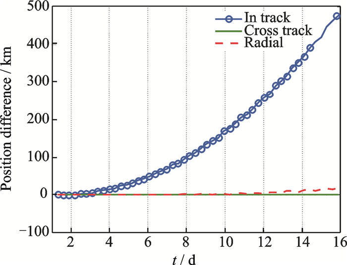
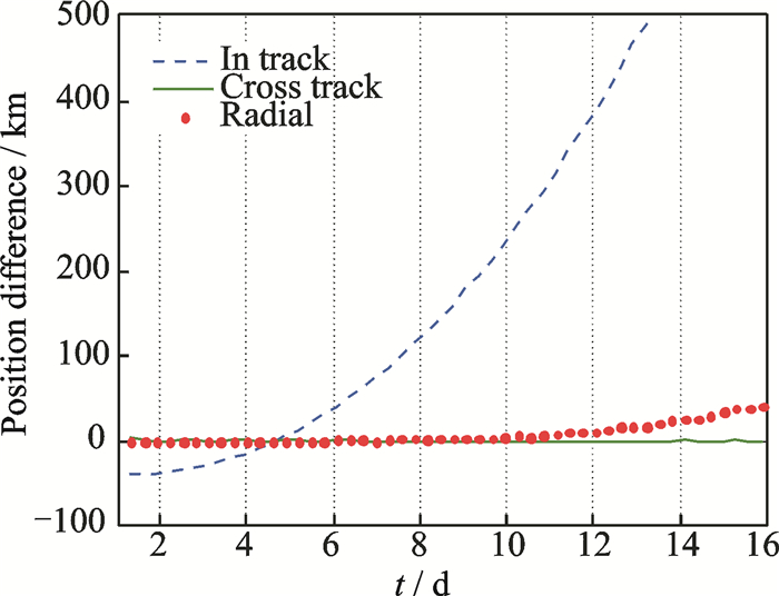
The satellite tool kit (STK) is used as an alternative for generating ephemeris, when real ephemeris is not available. Firstly, a high-precision orbital propagator (HPOP)[23] generates a 15 d nominal orbit at an altitude of 350 km with 0.000 1 eccentricity. Secondly, from a segment of that orbit, a TLE is generated using a 1 d fit span. The fit span is very important when generating the TLE (usually the period for generating a TLE in operation is 1-2 d). This TLE is considered as the NORAD TLE and hence a SGP4 orbit is generated. The position error between the two generated orbits is depicted in Fig. 1. It is obvious that the biggest error is in the in-track component, as previously discussed. The difference between the two orbits is there for a good measure of the TLE orbit error.
|
Fig. 1 TLE vs HPOP (ω= 63.746 9°, M= 15.038 4°) |
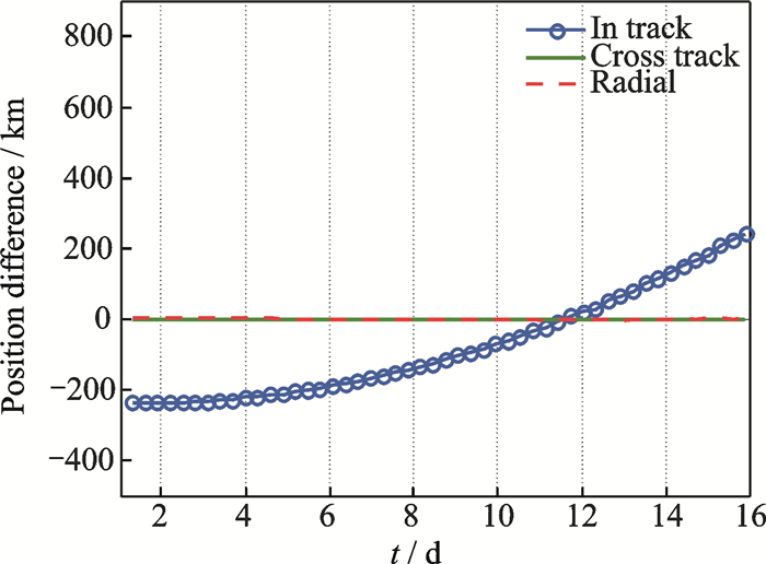
Considering Figs. 1, 2 with values for the angles (ω= 63.746 9°, M= 15.038 4°) and (ω= 62.746 9°, M= 14.038 4°), we realize that small change (±1°) in the angles results in obvious change in the in-track component and has no effect on the other two components. This is a little exaggerated but it can just indicate the direct connection between any change in the angles and the in-track error.
|
Fig. 2 TLE vs HPOP (ω= 62.746 9°, M= 14.038 4°) |
2.2 Generating the epoch TLE
The batch least squares state estimation algorithm was carried out in Matlab, and the only solved-for element the argument of latitude as introduced in Section 2.1. A Matlab code along with STK software was used to test and verify the OD algorithm. NJUST Ground Station was selected as the observation station. The nominal orbit and NORAD TLE were generated as introduced in Section 2.1. The initial conditions used in the simulation are listed in Table 1. They are very similar to NJUST2 initial conditions, which is one of the CubeSats of the QB50 mission. The epoch TLE is generated as follows.
| Table 1 Initial condition |
Considering Fig. 1, it is clear that the in-track error started to deviate nearly at the 5th day, reaching 30 km. A segment from the NORAD TLE orbit was used to generate a new TLE. The epoch of this TLE was the time of the satellite access over the ground station on the 5th day. The TLE is named "access epoch TLE" to prevent confusion with the NORAD TLE. Range rate data was generated from the nominal orbit simulating the measured range rate. They were generated around the same epoch under consideration and the measurement interval was 1. It was desirable to select a pass which has a reasonable length of time, about 5-10 min on the same day.
In the Matlab code, the angles (ω, M) were solved-for individually, instead of their sum directly. A is a (1×2) matrix. It evaluates the correction at each measurement time such that
| $ \begin{array}{l} \mathit{\boldsymbol{A}}\left( {i, 1} \right) = \frac{{\partial {{\dot \rho }_i}(\omega )}}{{\partial \omega }} \cong \frac{{{{\dot \rho }_i}(\omega + {\mathit{\Delta }_\omega }) - {{\dot \rho }_i}\left( \omega \right)}}{{{\mathit{\Delta }_\omega }}}\\ \mathit{\boldsymbol{A}}\left( {i, 2} \right) = \frac{{\partial {{\dot \rho }_i}(M)}}{{\partial M}} \cong \frac{{{{\dot \rho }_i}(M + {\mathit{\Delta }_M}) - {{\dot \rho }_i}\left( M \right)}}{{{\mathit{\Delta }_M}}} \end{array} $ | (7) |
The corrected ω and M are as follows
| $ \left[\begin{array}{l} \delta \omega \\ \delta M \end{array} \right]{\rm{ }} = {({\mathit{\boldsymbol{A}}^{\rm{T}}}\mathit{\boldsymbol{A}})^{ - 1}} \cdot \mathit{\boldsymbol{A}}\delta \dot \rho $ | (8) |
The inputs to run the Matlab code were the measured range rate and access epoch TLE. Results are declared in Table 2, namely the test case NJUST2. The corrected angles were used to correct the initial epoch TLE. By comparing the corrected orbit with the nominal orbit, it is found that the in-track error has decreased from 30 km to the range of 0-2 km. This is clear when comparing Fig. 1 and Fig. 3 at the 5th day which is the epoch under consideration.
| Table 2 Results before and after applying the correction algorithm using uM |

|
Fig. 3 Modified TLE vs HPOP |
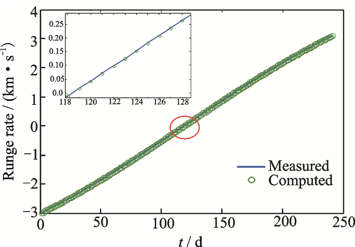
The Doppler shift measurements of a satellite pass over a tracking station presented an S-shape called Doppler curve of the pass, where it crossed the zero at the closest satellite approach, i.e. the highest elevation above the horizon. The measured and the computed range are plotted in Fig. 4.
|
Fig. 4 Measured and computed range rates |
3 Tests 3.1 Circular orbits at different inclinations
Further test cases to test and verify the angular correction OD technique was carried out. Circular orbits for CubeSats with different initial conditions are presented in Table 3.
| Table 3 Initial condition of HPOP orbits |
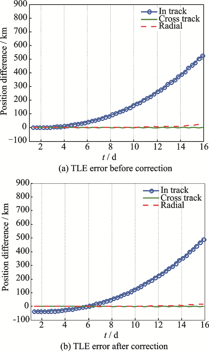
Table 2 shows results before and after applying the correction algorithm. Figs. 5-6 show the TLE cases 1, 2. As shown in Figs. 5-6, the error before and after the correction process for test dropped to 0±2 km (this is clear when comparing the TLE error before correction and TLE error after correction for the same test case), at the epoch where the correction process occurred at 6th and 5th days, respectively.
|
Fig. 5 Test case 1 |

|
Fig. 6 Test case 2 |
From Table 2, the test cases 3 and 4 have diverged. To find the reason for this divergence an important definition must be introduced: Observability which indicates the ability to uniquely determine the state from the corresponding observations[22]. These observations depend on the site's location. The partial derivatives in the correction matrix A are too small due to the low observability, causing the divergence in low inclination orbit cases. For that reason, the site's location must be changed for better observability and to overcome the divergence. In the simulation scenario the ground station location is changed to [0°, -60°]. The ground station was chosen to be located on the equator so that the equatorial and low inclined orbits were observable. For further analysis and to cover the low inclination orbits, five more test cases were introduced with inclinations (0°-40°) in order to determine the boundaries of the angular correction with inclination and to analyze its accuracy. Table 4 shows the initial conditions for the HPOP orbits. They are the same for all the following five test cases only the inclination changes and each test case is named for its assigned inclination.
| Table 4 Initial condition for HPOP orbits except inclination |
After correction using um, the convergence occurred, but not in the error dropped to the range 0-2 km as the cases with higher inclination, instead of all cases. To see and analyze the amount of error decrease, another angle was introduced and corrected so as to be compared with the um correction results. The mean longitude λm is defined as follows
| $ {\lambda _M} = \mathit{\Omega } + \omega + M $ | (9) |
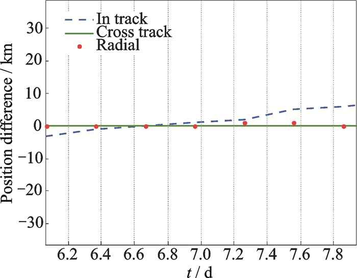
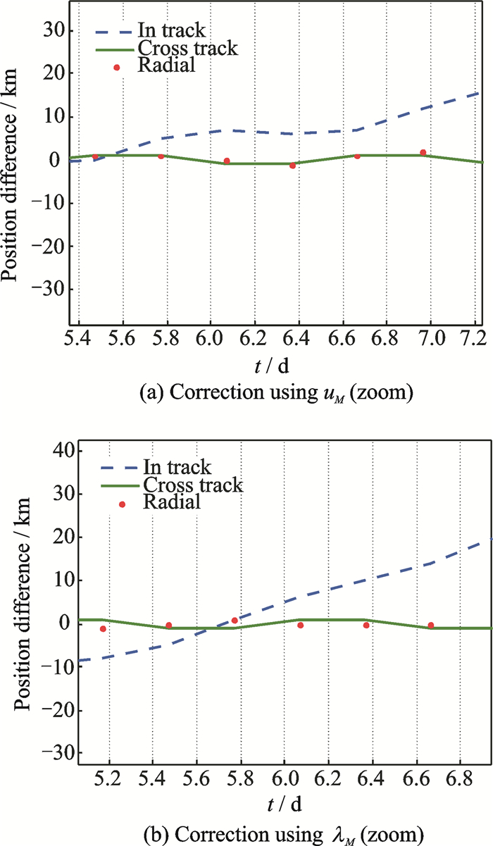
In the batch least squares, λM was the solved-for parameter accounting for the total angular error. The angle Ω presented the additional effect between the angle λM and uM. In Tables 5, 6, the results of the simulation for various test cases are tabulated declaring the computed values before and after correction using angles uM and λM, respectively. Figs. 7-10 show the in-track error after correcting using both angles uM and λM for the [0°, 5°, 10°, 20°] inclination, respectively.
| Table 5 Results before and after applying the correction algorithm using uM |
| Table 6 Results before and after applying the correction algorithm using λM |
|
Fig. 7 0° case: Correction using λM (zoom) (same as uM correction results) |
|
Fig. 8 5° case |

|
Fig. 9 10° case |
|
Fig. 10 20° case: Correction using λM(same as uM correction results) |
It was found that there was no difference between the two angles corrections at 0° inclination Fig. 7 shows the result. In the 5° case, when correcting-for uM, the error dropped to 6-7 km (noticing that the initial error for this case was 11±3 at the 6th day), while correcting-for λM the error dropped to 3-4 km, as shown in Fig. 8. There was a 3 km difference between the corrections of the two angles at that inclination. This difference was due to the addition of Ω in the correction process which is seen through the angle λM. For the 10° case, the error dropped from 31±2 km at the 6th day to 8-9 km using uM while using λM dropped to 4-5 km, as shown in Fig. 9. In the 20° case, there was no difference between the two angle corrections, either as depicted in Fig. 10. In the 40° inclination case, uM, λM correction results were identical. This indicates that at inclinations 20° and above, the effect of RAAN disappears and the angular correction using uM is sufficient. There is an error ranging from 3-5 km in inclinations less than 20° using λM. This indicates that an angular correction is not enough when really high precision is needed, but when coarse accuracy is needed it is acceptable. The angular correction can hence be carriedout depending on the inclination of the orbit. For inclinations higher than 20°, the correction using uM was sufficient, while for orbits with inclinations less than 20°, the λM was preferred for providing better accuracy.
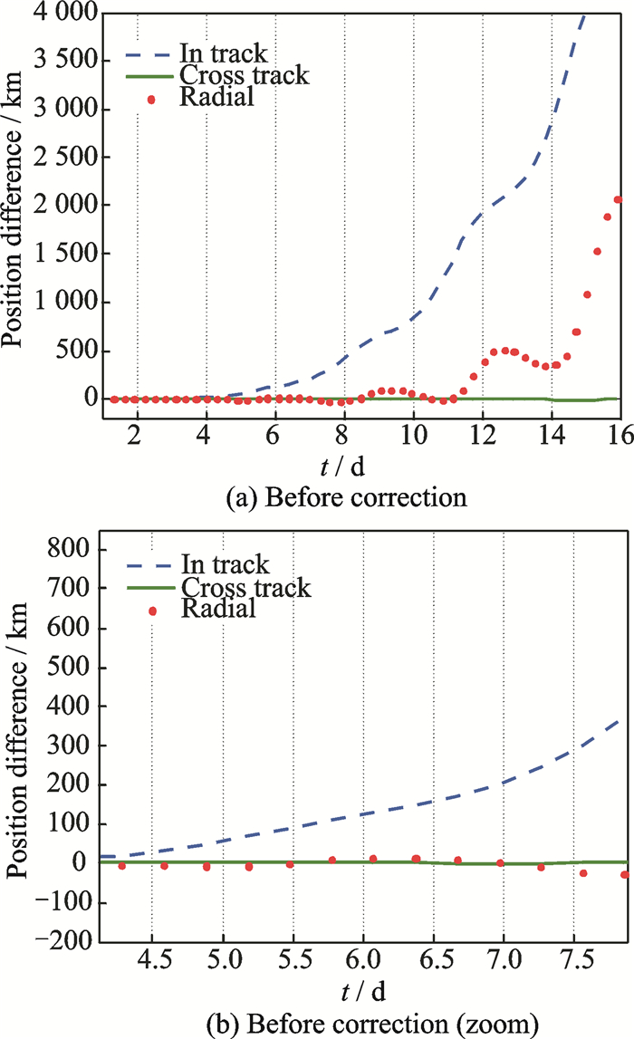
3.2 An elliptical caseThe initial conditions for an elliptical case are listed in Table 7. The initial error was 109 km at the 6th day and configured in Fig. 11. A new angle was introduced for clearer analysis. The longitude of periapsis
| $ \tilde \omega = \mathit{\Omega } + \omega $ | (10) |
| Table 7 Initial condition for the HPOP orbit of the elliptical case |
|
Fig. 11 Initial error of the elliptical case |
We chose the [0°, -60°] as the ground station coordinates in this simulation scenario. For this elliptical case, the corrections of uM and
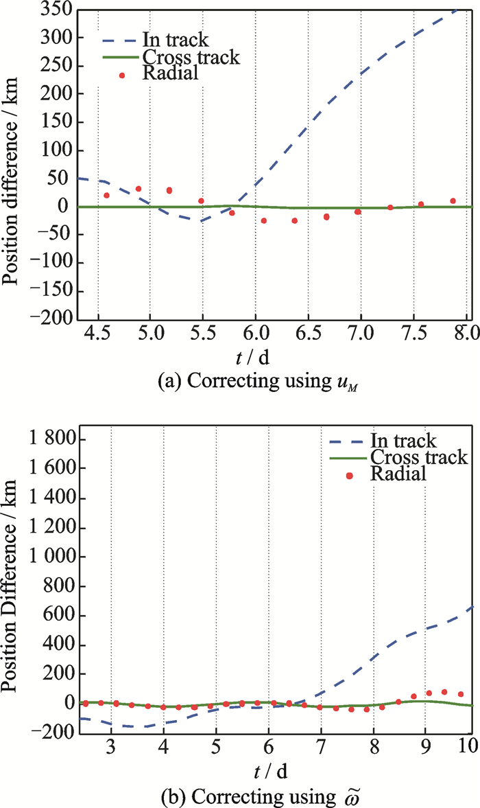
|
Fig. 12 Elliptical case |
After correcting using the angle uM, the error dropped from 109 km to 50 km. This error is not acceptable and indicates that the correction for uM is only applicable for circular orbits. The correction for
Elliptical orbits are not the best choice for LEO, since circular orbits are more preferable. It is realized that the error propagates quickly as time advances not only in the in-track component but also in the radial component. More analysis concerning elliptical cases will be presented in future work. This analysis indicates that the correction using uM is exclusive for circular orbits and that the angular correction is related to the orbit type.
4 ConclusionsA very effective and low cost OD technique for CubeSats in LEO was carried out self-dependently. It was verified using Matlab code and STK. The OD was effectively used to avoid error propagation of the TLE by correcting the in-track error significantly at the epoch under consideration. An angular correction was conducted by solving-for the mean argument of latitude in a batch least squares method. This method of OD is applied for satellites in circular orbits only because for an elliptical case the error was not acceptable even when coarse accuracy is needed. W hen introducing the longitude of periapsis to correct the angular error, the error dropped from 109 km to 0 km at the considered epoch. Although elliptical orbits are not the best choice for LEO, the angular correction was carried to know its limits and boundaries. It was seen that the angular correction depended on the orbit type and based on
The sequence in the analysis was intentional to see the problems when applying the angular OD. It depends on the ground station location and its observability for different circular orbits with different inclinations. The angular OD was applied on orbits with inclinations ranging from (0° to 98°) to provide a complete study on its accuracy and its relation with inclination.At different inclinations, the choice of the more suitable angle for the correction process will provide higher accuracy. For inclinations 20°and above, uM is sufficient while for inclinations less than 20°, λM provides better accuracy than uM. The in-track error ranged from 0-2 km in inclinations 20° and higher while the error ranged from 2-8 km in inclinations less than 20° after correcting uM. For inclinations less than 20°, the error ranged from 3-5 km when correcting λM. This angular correction technique can be considered as a backup procedure when normal procedures assigned for a certain mission fail depending on your own ground station for correction. Due to the lack of real data, the method was only verified through simulation which provided very promising results. It is known that when using real data, the error is expected to be increased. For future work, an effective way is to compare the results with real satellite ephemeris when available for more accurate verification and test the technique when real Doppler measurements available. More analysis concerning elliptical orbits can be carried out involving higher altitudes for flexibility.
Acknowledgements
The research was supported by the Research Fund for the Doctoral Program of Higher Education of China (No.20113219110025).
| [1] |
SELVA D, KREJCI D. A survey and assessment of the capabilities of CubeSats for earth observation[J]. Acta Astronautica, 2012, 74(27): 50-68. |
| [2] |
BOUWMEESTER J, GUO J. Survey of worldwide pico-and nanosatellite missions, distributions and subsystem technology[J]. Acta Astronautica, 2010, 67(7): 854-862. |
| [3] |
WOELLERT K, EHRENFREUND P, RICCO A J, et al. CubeSats:Cost-effective science and technology platforms for emerging and developing nations[J]. Advances in Space Research, 2011, 47(4): 663-684. DOI:10.1016/j.asr.2010.10.009 |
| [4] |
MUYLAERT J, REINHARD R, ASMA C, et al. QB50: An international network of 50 CubeSats for multi-point in-Situ measurements in the lower thermosphere and for re-entry research[C]//ESA Atmospheric Science Conference. Barcelona, Spain: [s.n.], 2009: 7-11.
|
| [5] |
GILL E, SUNDARAMOORTHY P, BOUWMEESTER J, et al. Formation flying within a constellation of nano-satellites:The QB50 mission[J]. Acta Astronautica, 2013, 82(1): 110-117. DOI:10.1016/j.actaastro.2012.04.029 |
| [6] |
BEDON H, NEGRON C, LLANTOY J, et al. Preliminary internetworking simulation of the QB50 CubeSat constellation[J]. Communications, 2010, 1-6. |
| [7] |
MARSZALEK M, KURZ O, DRENTSCHEW M, et al. Inter-satellite links and relative navigation:Pre-conditions for formation flights with pico-and nanosatellites[J]. World Congress, 2011, 44(1): 3027-3032. |
| [8] |
ROGERS A Q, PAXTON L J, DARRIN M A. Small satellite constellations for measurements of the near-earth space environment[C]//Small Satellite Missions for Earth Observation. Berlin, Germany: [s.n.], 2009: 113-121.
|
| [9] |
BLACKWELL W, ALLEN G, GALBRAITH C, et al. Nanosatellites for earth environmental monitoring: The MicroMAS project[C]//32nd IEEE International Geoscience and Remote Sensing Symposium. [S.l.]: IEEE, 2012: 206-209.
|
| [10] |
BYRON D, TAPLEY, BOB E, at el. Satellite orbit determination[M]. 1st ed. [S.l.]: Academic Press, 2004.
|
| [11] |
VALLADO D A, CRAWFORD P, HUJSAK R. Revisiting spacetrack report #3[C]//AIAA/AAS Astrodynamics Specialist Conference and Exhibit. Keystone, Calorado: AIAA, 2006.
|
| [12] |
VALLADO D A, CRAWFORD P. SGP4 orbit determination[C]//AIAA Guidance, Navigation, and Control Conference and Exhibit. Honolulu, HI: AIAA, 2008.
|
| [13] |
HOOTS F R, ROEHRICH R L. Spacetrack report #3: Models for propagation of the NORAD element sets[R]. Spacetrack Report, 1980.
|
| [14] |
LONG A C, CAPPELLARI J O, FUCHS A J, et al. Goddard trajectory determination system (GTDS) mathematical theory[M]. [S.l.]: Goddard Space Flight Center, 1989.
|
| [15] |
COYLE D, PERNICKA H J. Orbit determination at a single ground station using range rate data[J]. Journal of the Astronautical Sciences, 2001, 49(2): 327-344. |
| [16] |
SAKAMOTO Y, KASAHARA Y, YASAKA T. Low-cost orbit determination system for a CubeSat[J]. IPSI Sig Notes, 2003, 96(113): 39-50. |
| [17] |
CHUNYIH H, DAYUNG K, RAHMAN O, et al. Low-cost rapid TLE updating method for nano-satellites using doppler signature[C]//AIAA Space Conference & Exposition. Long Beach, California: AIAA, 2011.
|
| [18] |
KELSO T S. Validation of SGP4 and IS-GPS-200D against GPS precision ephemerides[C]//17th AAS/AIAA Space Flight Mechanics Conference. Sedona, Arizona: AIAA, 2007: AAS 07-127.
|
| [19] |
GANGESTAD J, HARDY B, HINKLEY D. Operations, orbit determination and formation control of the AeroCube-4 CubeSats[C]//27th Annual AIAA/USU Conference on Small Satellites. [S.l.]: AIAA, 1999: SSC 13-X-4. [HJ*5/9]
|
| [20] |
MONTENBRUCK O, GILL E. Satellites orbits:Models, methods, applications[M]. 3rd ed. New York: Springer Verlag, 2005.
|
| [21] |
LARSON W J, WERTZ J R. Space mission analysis and design[M]. 3rd ed. Torrance, CA: Springer, 2007.
|
| [22] |
VALLADO D A, WERTZ J R. Fundamentals of astrodynamics and applications[M]. 3rd ed. Hawthorne, CA: Springer/Microcosm, 2007.
|
| [23] |
SCHOLZ T, ASMA C O, ARULIAH A. Recommended set of models and input parameters for the simulations of orbital dynamics of the Qb50 Cubesats[R]. QB50 Committee, 2012: 1-8.
|
 2018, Vol. 35


