The blade is one of the most important components of aero-engine, which produces the power to propel the aircraft forward through blade interacting with the air flow. The vibration fatigue caused by periodic air flow is one of the main failure modes of blades. With the development of modern high thrust and high bypass ratio engine, blade vibration fatigue becomes more prominent. The failure of blade not only influences the performance reliability of whole engine but also threatens people's life. If blade resonance is inevitable, it has an engineering significance to predict accurately the vibration fatigue life for avoiding the occurrence of major accidents.
The vibration failure analysis and fatigue life prediction of blade damaged in engine operation have received extensive attention of investigations[1-7]. For instance, Zhang et al.[1] systematically introduced the fatigue failures, numerical simulations of fatigue, and fatigue test of impellers and blades in several typical turbo machines. It was pointed out that high cycle fatigue (HCF) caused by vibration was the main failure mechanism, fatigue cracks was initiated from the location of stress concentration, and the resonance caused by the aerodynamic load was the main cause of fatigue failure of impellers and blades in a steady operating condition. Witek[2] conducted the experimental and numerical analysis to investigate both crack propagation and damage process of the compressor blade subjected to high cycle fatigue, and pointed that the transverse vibrations can be very dangerous for compressor blades because of large levels of stress occurring during resonance. Zucca[4] proposed a method to evaluate the friction damping due to the relative tangential motion on the blade root joints and computed its impact on the forced response of bladed disks.
In the engineering practice, there are many uncertain factors during design, manufacture and operation, such as material properties, geometric dimension, external excitation and so on. It is not accurate and has shortages to employ the deterministic approaches to evaluate the fatigue life of the blade. Many researches show that probabilistic approach is effective on predicting fatigue life of blade[8-11]. Zhang et al. [8] proposed a probability method called PHBA for prediction on HCF of blades caused by aerodynamic loads. Based on the PHBA, the probabilistic accumulative damages altering with operation time were calculated, and the operational reliabilities were also obtained. Lin et al. [9] proposed an improved stress-strength interference (SSI) model and nonlinear residual strength model to analyze the reliability of aero-engine blades with the fatigue failure mode. The results show that an important advantage of the nonlinear residual strength model and the improved SSI model compared to classical approach is their applicability to any actual component through the finite element (FE) technique. Gao et al.[10] applied the collaborative response surface method to the reliability analysis of turbine blade low-cycle fatigue damage. Through the comparison of methods, it reveales that distributed collaborative response surface method is superior to response surface method in computational precision and efficiency, especially for low confidence level.
In most of practical applications involving probabilistic fatigue life analysis of blade, the reliability function is defined implicitly, and its evaluation requires numerical response calculations by means of finite element analysis (FEA). There are several different possible methods for reliability analysis with implicit reliability function. Those methods mainly contain the first-order second-moment (FOSM)[12], second-order second-moment (SOSM)[13], response surface method (RSM)[8, 10] and Monte Carlo method (MCM)[14]. However FOSM and SOSM are only applied to the low nonlinear reliability problem and possess low analytical precision for high nonlinear reliability problems. The conventional RSM requires large computational efforts and shows loss of accuracy in the case of problems exhibiting acute nonlinearity. The MCM holds low computation efficiency and the simulation credibility depends on the size of samples[10].
The maximum entropy method is a distribution free technique for estimating the reliability function of the response such as cumulative distribution function (CDF). It is widely studied and recognized as an efficient stochastic modeling tool when a small number of samples is available[15-18]. Pandey[15] proposed a distribution free method for estimating the quantile function of a non-negative random variable using the principle of maximum entropy subjected to constraints specified in terms of the integral-order probability-weighted moments (IPWM) estimated from observed data. Deng[16] proposed the fractional probability weighted moments (FPWM) based quantile function to improve the computational accuracy of IPWM based quantile function. Deng[17] proposed a distribution free method for the estimation of the quantile function of random variable using a censored sample of data, which was based on the principle of partial maximum entropy with constraints in terms of partial probability-weighted moments (PPWM).
Bending vibration fatigue is one of the main failure modes of blade. When the blade is subjected to bending vibration, there exists stress gradient in the thickness direction. The fatigue prediction accuracy of blade can be improved through considering the effect of stress gradient. In the engineering practice there are many researches about the effect of stress gradient on the fatigue life prediction[19-21]. Qylafku et al.[19] introduced a new macro-mechanical model for fatigue life prediction, considering an elastic-plastic stress distribution and the stress gradient evolution. Adib-Ramezani et al.[20] proposed a new method called polynomial volumetric method, which satisfies weight function conditions, removes numerical derivation errors and elucidates effective stress terms as subtraction of average stress and relative stress gradient based phrase. Moustabchir et al.[21] proposed a safety methodology to detect the boundary of failure assessment diagram (FAD), as a new solution to predict the service life of pipeline products. The methodology was connected to the modified FAD approach, whereas the specific parameters were settled using the volumetric method calculation, based on the notch stress intensity factor determined in the elasto-plastic field. However, the volumetric method applied by these literatures to study the effects of stress gradient is one-dimensional, so it is not convenient to use such the method to predict the fatigue life of actual three-dimensional engineering structure.
In this paper, compared with one-dimensional volumetric method (ODVM) firstly, a three-dimensional space vector volumetric method (TSVVM) is proposed to improve fatigue life prediction accuracy for actual three-dimensional engineering structure. Secondly, based on the volumetric method (ODVM or TSVVM), material C-P-S-N fatigue curve model (CFCM) and maximum entropy quantile function model (MEQFM), a vibration fatigue probabilistic life prediction model (VFPLPM) is built and a method is established to predict the vibration probabilistic life of blade. Finally, the vibration test and numerical simulation of blade simulator are conducted to verify the validation of the VFPLPM and method.
1 Experiments 1.1 Ti2AlNb titanium-aluminium alloy fatigue testTi2AlNb titanium-aluminium alloy is a kind of casting alloy, whose nominal chemical composition is Ti22Al24Nb. It has excellent comprehensive properties, and is mainly applied in the fan blade and compressor wheel and blade.
The tension-compression symmetric fatigue test of Ti2AlNb was conducted under stress control on the fatigue testing machine (Fig. 1) with room temperature (25 ℃) and 10 Hz test frequency. The test specimens were designed and manufactured to round dumbbells(Fig. 2). Four test stress levels, 80%σb, 70%σb, 60%σb, and 50%σb were chosen, where σb is the ultimate stress and the value is 1 212.592 MPa. The fatigue life of each specimen was obtained while fracture failure occurred. Different numbers of fatigue test data could be obtained on each stress level.

|
Fig. 1 SDS-50 electro hydraulic servo dynamic static and dynamic testing machine |

|
Fig. 2 Tension and compression fatigue test specimen |
1.2 Vibration fatigue test of blade simulator
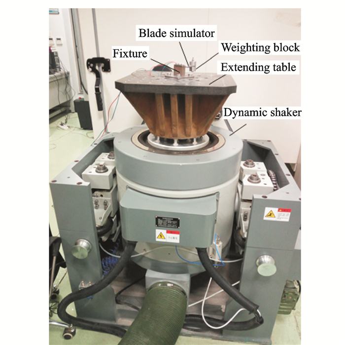
The blade simulator (Ti2AlNb titanium-aluminium alloy flat plate with notches, Fig. 3) was adopted because of the complex shape and high processing cost. Moreover, the vibration forms and characteristics of external excitations are different, such as wake excitation, inlet flow distortion, and rotating stall. In this section, foundation excitation vibration fatigue test was adopted to verify the VFPLPM. Fig. 4 shows the foundation excitation vibration fatigue test equipment.

|
Fig. 3 Blade simulator specimen |
|
Fig. 4 Vibration fatigue test equipment |
In order to study the vibration fatigue probabilistic life of blade simulator, 15 test samples were designed based on the uniform design table [22, 23]. The probability distribution and sample values of design parameters and vibration fatigue test results are listed in Tables 1-2.
| Table 1 Experimental design parameters and vibration fatigue test results |
| Table 2 Probability distribution of design parameters and vibration fatigue test results |
There were four steps to obtain those sample values of the design parameters and results of vibration fatigue.
(1) The length, width and height of blade simulator could be measured by vernier caliper. The density could be estimated by mass and volume which were measured by FA2004CS electronic scales and UG software respectively.
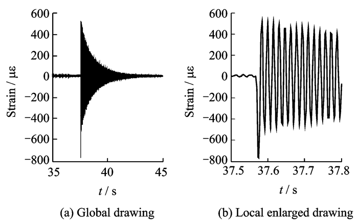
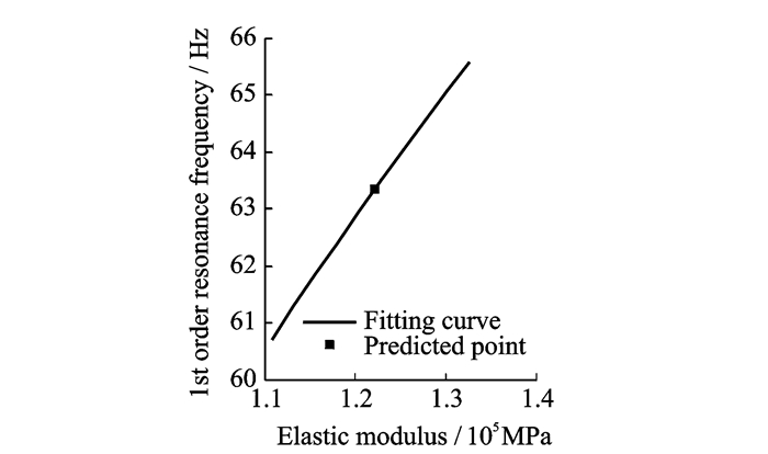
(2) The estimation of elastic modulus of each blade simulator. ①The 1st order resonance frequency of each blade simulator could be obtained by free decay oscillation method. After hammering the simulator blade, the strain response was collected and processed by NI SCXI-1000 (Figs. 5-6). The 1st order resonance frequency of each blade simulator is equal to the period of oscillation of the strain time curve. ② The functional relationship between 1st order resonance frequency and elastic modulus could be obtained by finite element analysis and polynomial fitting (Fig. 7). The elastic modulus of each blade simulator was estimated through polynomial fitting at corresponding 1st order resonance frequency.

|
Fig. 5 Position of hammer point and strain gauge |
|
Fig. 6 Strain time curve of 8# blade simulator |
|
Fig. 7 Functional relationship between 1st order resonance frequency and elastic modulus of 8# blade simulator |
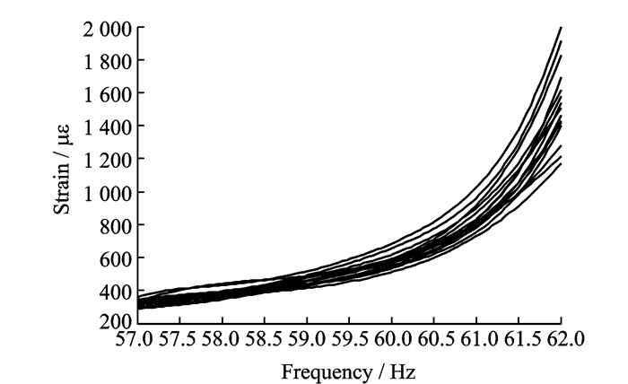
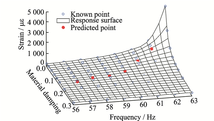
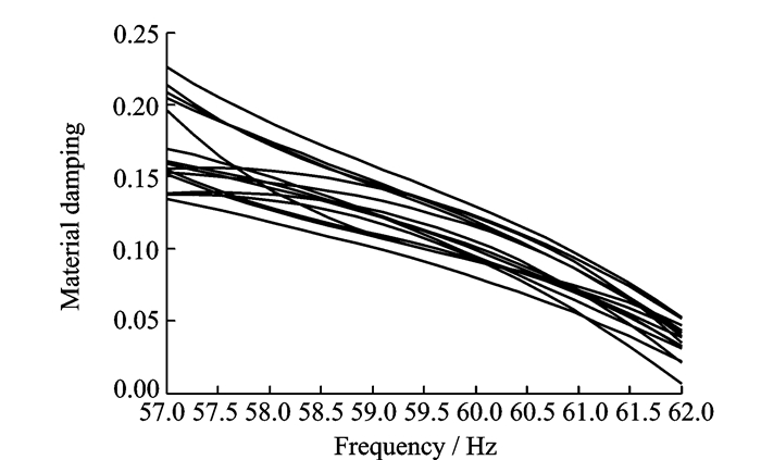
(3) The estimation of the material damping of blade simulator. ① 15 blade simulators were subjected to the single frequency harmonic foundation excitation with excitation amplitude 9 806.65 mm/s2 and excitation frequency range 57—62 Hz. The strain responses of 15 blade simulators were collected and processed by NI SCXI-1000 (Fig. 8). ② The functional relationship among material damping, excitation frequency and strain response could be obtained by the finite element analysis and B spline interpolation surface method (Fig. 9). The material damping of each blade simulator could be estimated by the interpolation surface at corresponding excitation frequency and strain response (Figs. 9-10). It is shown that material damping decreases with the increase of excitation frequency, and material damping at each excitation frequency are dispersed.
|
Fig. 8 Functional relationships between strain response and excitation frequency of 15 blade simulators |
|
Fig. 9 Interpolation surface of excitation frequency, material damping and strain response of 8# blade simulator |
|
Fig. 10 Functional relationships between material damping and excitation frequency of 15 blade simulators |
(4) Vibration fatigue test. The blade simulator was mounted on the dynamic shaker through the fixture (Fig. 4) to be subjected to single frequency harmonic foundation excitation. The vibration fatigue lives of blade simulators were obtained when the fracture failure occurred under designed excitation amplitude and frequency listed in Table 1.
2 VFPLPM and MethodThe vibration fatigue life of blade is scattered because of manufacture error, material property dispersion and external excitation randomness. It is significant to establish vibration fatigue probabilistic life prediction model (VFPLPM) and method.
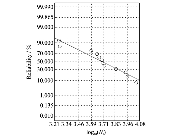
2.1 C-P-S-N fatigue curve model (CFCM)From the Ti2AlNb titanium-aluminium alloy fatigue test (see Section 1.1), different numbers of fatigue test data on each stress level could be obtained. It is verified that fatigue test data of each stress level follow the lognormal distribution (Fig. 11).
|
Fig. 11 Normal distribution fitting of logarithmic fatigue life of 80%σb stress level |
According to the existed error between the estimated distribution parameters and real value on the small samples, scatter factor method (SFM)[18] is introduced to improve confidence level of distribution parameter estimation.
The fatigue test data of each stress level are represented by random variable X with the order statistics (x(1)≤x(2)≤…≤x(n)), and the random variable Y=lgX follows normal distribution. The quantile function Q(γ, p) of random variable X with confidence level γ, and reliability p can be presented as
| $ \left\{ \begin{align} &{{Q}_{1}}\left( \gamma, p \right)=\frac{{{x}_{(1)}}{{10}^{{{F}^{-1}}}}({{\mu }_{Y}}, {{\sigma }_{Y}}, 1-p)}{{{10}^{{{F}^{-1}}}}({{\mu }_{Y}}, {{\sigma }_{Y}}, 1-{{p}_{(1)}})} \\ &{{Q}_{n}}\left( \gamma, p \right)=\frac{{{x}_{(n)}}{{10}^{{{F}^{-1}}}}({{\mu }_{Y}}, {{\sigma }_{Y}}, 1-p)}{{{10}^{{{F}^{-1}}}}({{\mu }_{Y}}, {{\sigma }_{Y}}, 1-{{p}_{(n)}})} \\ &Q\left( 0.5, p \right)={{10}^{{{F}^{-1}}}}({{\mu }_{Y}}, {{\sigma }_{Y}}, 1-p) \\ \end{align} \right. $ | (1) |
where Q1(γ, p) is the quantile function based on minimum order statistic SFM, Qn(γ, p) is the quantile function based on maximum order statistic SFM, Q(0.5, p) is the quantile function with 50% confidence level. F-1(μY, σY, 1-p) is the quantile function value of random variable Y with reliability p where F-1(·) is the inverse function of cumulative distribution function.μY, σY are the mean value and standard deviation of Y, respectively.

|
Fig. 12 Confidence interval estimation of fatigue life of 80%σb stress level |
Based on the quantile function Q(γ, p) of each stress level, the C-P-S-N fatigue curve model is defined as [24]
| $ \left(s-{{s}_{\text{cpsn}}}\left( \gamma, p \right)\right){{~}^{{{m}_{\text{cpsn}}}}}\left( \gamma, p \right){{N}_{f}}={{c}_{\text{cpsn}}}\left( \gamma, p \right) $ | (2) |
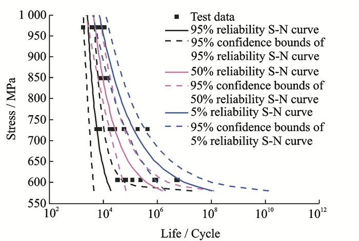
where scpsn(γ, p), mcpsn(γ, p), ccpsn(γ, p) are the fatigue curve parameters, which are estimated by the quantile function value of each stress level with confidence level γ and reliability p.s is the stress level and Nf is the fatigue life. Finally, the fatigue curve of Ti2AlNb titanium-aluminium alloy with confidence level γ and reliability p can be estimated by Eq.(2)(Fig. 13).
|
Fig. 13 C-P-S-N fatigue curve of Ti2AlNb titanium-aluminium alloy |
2.2 Maximum entropy quantile function model (MEQFM)
Compared with the traditional probability distribution hypothesis and parameter estimation method, maximum entropy method is a distribution free technique, which is more efficient and flexible. The maximum entropy quantile function model QMEM(u) of random variable G can be written as [15-18]
| $ {{Q}_{\text{MEM}}}\left( u \right)=\text{exp}\left( -\sum\limits_{j=0}^{m}{({{\lambda }_{j}}{{u}^{j}})} \right) $ | (3) |
The relationship with Lagrange multipliers[15-18] is
| $ {{\lambda }_{0}}=\text{ln}\left[\int_{0}^{1}{\text{exp}\left(-\sum\limits_{j=0}^{m}{({{\lambda }_{j}}{{u}^{j}})}~\text{d}\mathit{u}/{{\mathit{b}}_{0}} \right)} \right]~ $ | (4) |
where u is the cumulative probability function value of random variable G.λj(j=0, 1, …, m) are the Lagrange multipliers, and can be estimated by solving follow optimization problem[15-18]
| $ \text{Min}~\ \ \mathit{W}=\sum\limits_{j=0}^{m}({{{\lambda }_{j}}{{b}_{j}}}) $ | (5) |
where bj(j=0, 1, …, m) are the one form of probability weighted moments (PWMs), and m is the highest order of PWMs considered in the analysis.
From an ordered random sample of G with size n(g1≤g2≤…≤gn), bj can be obtained as[15-18]
| $ {{b}_{j}}=\frac{1}{n}\sum\limits_{i=1}^{n}{\left[\frac{C\left( i-1, j \right)}{C\left( n-1, j \right)}{{g}_{i}} \right]~} $ | (6) |
After Lagrange multipliers {λj}j=0m are determined, the quantile value of random variable G for the cumulative distribution function value u could be estimated by Eq.(3).
2.3 Three-dimensional space vector volumetric method (TSVVM)The vibration fatigue failure caused by air flow excitation is one of the main failure modes of blade, and bending vibration is common in the actual situation. Because it has the stress gradient in the blade thickness direction when blade is subjected to bending vibration, it is significant to consider the effect of stress gradient for improving the prediction accuracy of fatigue life.
According to the volumetric method, the fatigue damage of structure is not only relative to the maximum stress but also relative to the stress distribution around maximum stress position. The equivalent stress sVM is used to describe the effect of stress distribution around the maximum stress position, and the most common formula sODVM of sVM based on one-dimensional volumetric method is defined as[19-21]
| $ {{s}_{\text{ODVM}}}=\frac{1}{{{l}_{\text{eff}}}}\int_{0}^{{{l}_{\text{eff}}}}{\left[f\left( {{s}_{ij}}, l \right)\left( 1-\chi l~ \right) \right]}\text{d}\mathit{l} $ | (7) |
where leff is the effective distance, which is along with the crack direction.f(sij, l) is the function of stress component sij at the l distance, which is usually the principal stress or von Mises stress.χis the relative stress gradient and l is the distance between the calculation point and dangerous point (maximum stress position).
The relative stress gradient χ is defined as [19-21]
| $ \chi =\frac{1}{f\left( {{s}_{ij}}, l \right)}\frac{\text{d}\mathit{f}\left( {{s}_{ij}}, l \right)}{\text{d}\mathit{l}} $ | (8) |
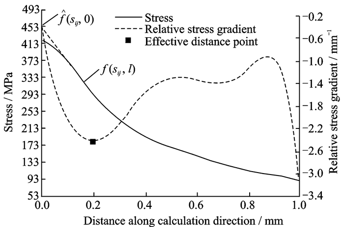
The effective distance leff is determined as the distance between the first local minimum point of relative stress gradient curve and the dangerous point (Fig. 14). It is thought that there exists the stress relaxation at the effective distance point. In this paper, the equivalent stress sOVM defined by Eq.(7) is called one-dimensional volumetric method (ODVM).
|
Fig. 14 Stress and relative stress gradient distribution around the dangerous point |
The physical meaning of Eq.(7) can be interpreted that the stress function
To improve the computational accuracy of equivalent stress by considering the stress gradient effect of other space vector directions, a new three-dimensional volumetric method called three-dimensional space vector volumetric method (TSVVM) is proposed. The equivalent stress sTSVVM based on TSVVM is defined as
| $ {{s}_{\text{TSVVM}}}=\frac{1}{N}\sum\limits_{k=1}^{N}{{{s}_{\text{ODVM}(k)}}\text{cos}\theta } $ | (9) |
where sODVM(k) is the equivalent stress of kth calculation direction r, N is the number of calculation direction, θ is the angle between r and rmax, and rmax is the calculation direction with maximum average stress gradient.
There are two problems needed to be solved before applying Eq.(9):
(1) Determination of calculation directions
① Make a calculation sphere Sc with radius r and mark the dangerous point of engineering structure as center (usually, r=1—2 mm on the actual situation).
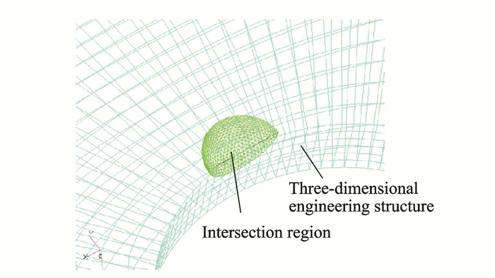
② Determine the intersection region between the three-dimensional engineering structure and calculation sphere (Fig. 15).
|
Fig. 15 Intersection region between three-dimensional engineering structure and calculation sphere |
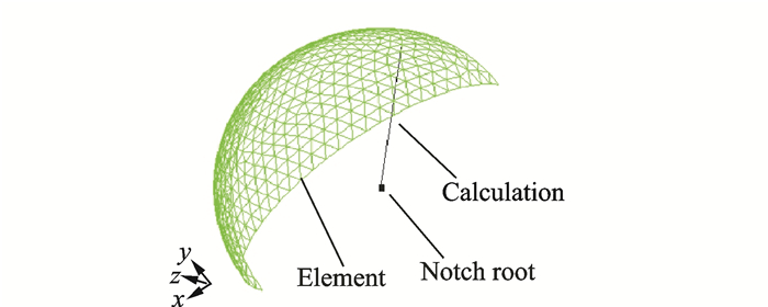
③ Mesh the calculation sphere surface of intersection region by the triangular element with 0.1 mm size (Fig. 16).
|
Fig. 16 Spatial calculation direction |
④ Obtain a calculation direction by lining dangerous point and element node (Fig. 16).
⑤ Determine the N calculation directions by repeating the step④, where N is the number of element nodes.
(2) Determination of stress distribution on the calculation direction r
In the engineering practice, the spatial stress distribution of three-dimensional engineering structure is obtained by the finite element software, and it is saved as node stress. It needs to apply the three-dimensional interpolation technique to obtain the stress distribution on the calculation direction r.
The Kriging model is an interpolation technique based on statistical theory. It has several advantages, such as unbiased estimator at the training sample point, desirably strong nonlinear approximating ability, flexible parameter selection of the model and accurate global approximation ability. These advantages make it widely used in approximate models[25, 26]. In this section, Kriging model is applied to determine the stress distribution on the calculation direction r.
Generally, the steps of applying the TSVVM are:
(1) Obtain the stress distribution of engineering structure by the finite element software Patran & Nastran.
(2) Mark the maximum stress point as dangerous point.
(3) Determine the N calculation directions
(4) Obtain the stress distribution of calculation direction r by Kriging model and estimate the equivalent stress of calculation direction r based on Eq.(7).
(5) Determine the calculation direction rmax which has maximum average stress gradient.
(6) Estimate the equivalent stress sTSVVM based on Eq.(9).
2.4 Establishment of VFPLPM and methodBecause of the manufacture error, material property dispersion and external excitation randomness, the vibration fatigue life of blade is dispersed. VFPLPM is proposed based on the volumetric method, CFCM and MEQFM. The formula QVF(u, γ) of VFPLPM can be written as
| $ {{Q}_{\text{VF}}}\left( u, \gamma \right)=\text{exp}~\left( -\sum\limits_{j=0}^{t}{\left( {{\lambda }_{\gamma, j}}{{u}^{j}} \right)} \right) $ | (10) |
where QVF(u, γ) is the quantile function of blade vibration fatigue life with variable u and γ.u is the cumulative distribution function value. γ is the upper confidence limit.λγ, j is the Lagrange multiplier with upper confidence limit γ.t is the order of Lagrange multipliers. The Lagrange multipliers {λγ, j}j=0t can be estimated by the MEQFM and vibration fatigue life samples Lsample with upper confidence limit γ which is obtained by volumetric method (ODVM or TSVVM) and CFCM.
The detailed procedures of generating the vibration fatigue life samples Lsample with upper confidence limit γ are:
(1) Assuming that dimension parameters of blade (length, width, height), material property parameters (elastic modulus, density, reliability p of C-P-S-N fatigue curve, material damping) and external excitation (excitation amplitude and frequency) are random variables. Nsample design samples are generated based on the uniform design table[22, 23], and each of design samples is the combination of dimension parameters of blade, material property parameters and external excitation.
(2) Nsample equivalent stress samples ssample can be obtained based on the vibration fatigue finite element simulation of blade and volumetric method (ODVM, Eq.(7) or TSVVM, Eq.(9)).
(3) Nsample vibration fatigue life samples Lsample with upper confidence limit γ are obtained based on CFCM (Eq.(2)), design samples of reliability p of C-P-S-N fatigue curve and equivalent stress samples ssample.
3 Finite Element Simulation and Test VerificationAs the complex shape and high processing cost of real blade, the blade simulator (Fig. 3) was adopted. Moreover, the vibration forms and characteristics of actual external excitations are different, such as wake excitation, inlet flow distortion and rotating stall. It is complex and costly to conduct the test in the actual condition. In this section, foundation excitation vibration fatigue test was adopted to study the vibration fatigue probabilistic life prediction model (VFPLPM) and method.
In this section, dimension parameters of blade simulator, material property parameters and external excitation were treated as random variables. Vibration fatigue probability life of blade simulator was estimated by combining VFPLPM with maximum stress method (MSM), one-dimensional volumetric method (ODVM) and three-dimensional space vector volumetric method (TSVVM), respectively. Moreover, it was compared with the vibration fatigue test data for verifying VFPLPM, and then compared with the computational accuracy of three equivalent stress methods. The vibration fatigue test could be seen in the Section 2.2.
The reliability of C-P-S-N fatigue curve follows uniform distribution with value range from 0.025 to 0.975. The 200 design samples of foundation excitation vibration finite element simulation were generated by the uniform design table[22, 23] and corresponding simulation samples of vibration fatigue life of blade simulator were obtained by the MSM, ODVM and TSVVM, respectively. Finally the vibration fatigue probabilistic life of blade simulator was estimated based on the VFPLPM (Eq.(10)) and simulation samples of vibration fatigue life of blade simulator. The foundation excitation vibration finite element simulation of blade simulator is shown in Fig. 17.

|
Fig. 17 Finite element simulation of blade simulator |
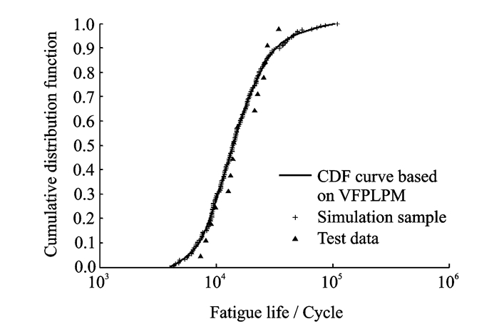
The cumulative distribution function (CDF) of vibration fatigue probabilistic life of blade simulator with 50% confidence level based on the VFPLPM+TSVVM method is shown in Fig. 18. It is showed that the cumulative distribution function curve is in good agreement with simulation samples and test data, and the VFPLPM+TSVVM method has higher accuracy (Note: Cumulative distribution function is the inverse function of qunatile function).
|
Fig. 18 Quantile function of vibration fatigue probabilistic life of blade simulator based on VFPLPM+TSVVM method |
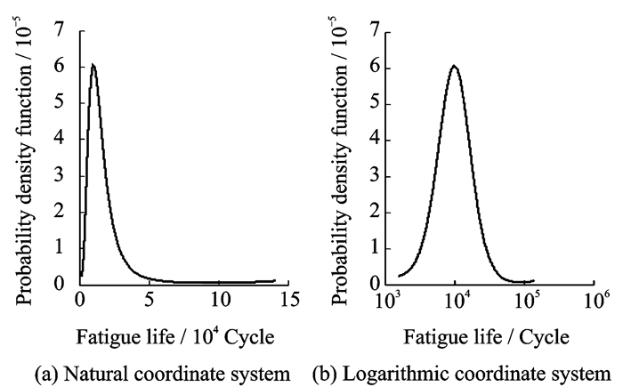
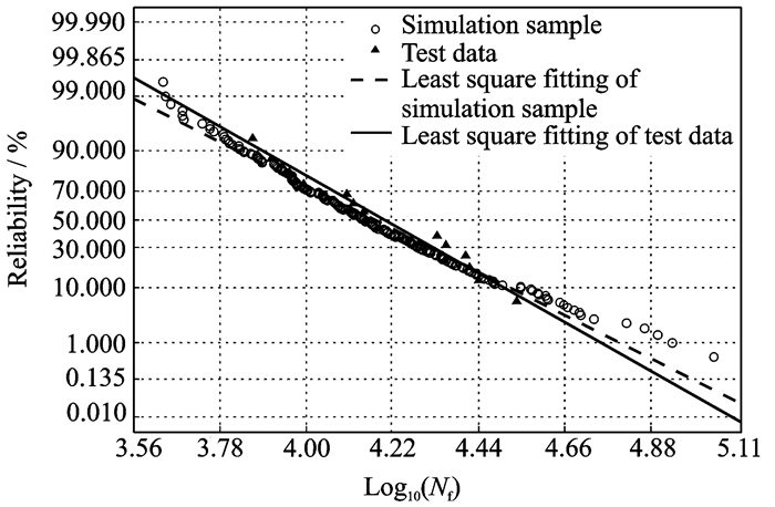
The maximum entropy probability density function (PDF) of vibration fatigue probabilistic life of blade simulator based on VFPLPM+TSVVM is shown in Fig. 19, and it shows that the predicted vibration fatigue life of blade simulator follows lognormal distribution. The simulation samples and test data were also verified by the traditional probability distribution hypothesis and parameter estimation method. Fig. 20 and Table 3 show that the simulation samples are coincident with test data with all obeying the lognormal distribution and having similar distribution parameters (Cumulative distribution functions and probability density functions of vibration fatigue probabilistic life of blade simulator based on the VFPLPM+MSM method and the VFPLPM+ODCV method have the same results with that based on the VFPLPM+TSVVM method, which are not discussed here).
|
Fig. 19 Maximum entropy probability density function of vibration fatigue probabilistic life of blade simulator based on VFPLPM+TSVVM method |
|
Fig. 20 Normal distribution fitting of logarithmic vibration fatigue probabilistic life of blade simulator |
| Table 3 Lognormal distribution parameters of vibration fatigue probabilistic life of blade simulator |
The ordered vibration fatigue test life Nf, test of blade simulator with Nf, test, 1≤Nf, test, 2≤…≤Nf, test, 15 is defined as middle rank test data, and the corresponding ordered cumulative distribution function value ui can be determined by the middle rank method[18], shown as
| $ {{u}_{i}}=\frac{i-0.35}{n} $ | (11) |
where ui is the ith ordered cumulative distribution function value, n is the number of vibration fatigue test life, here n=15.
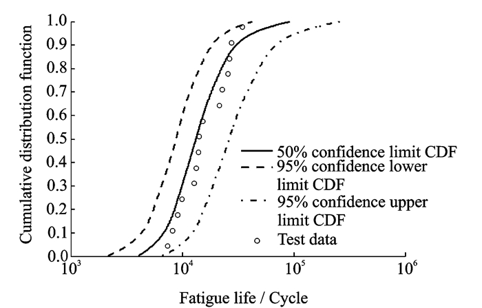
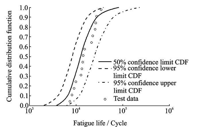
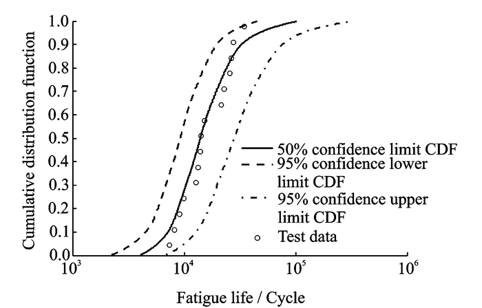
The comparisons of quantile function confidence interval estimation of vibration fatigue probabilistic life of blade simulator among three combination methods are showed in Figs. 21-23, and Table 4.
|
Fig. 21 Quantile function confidence interval estimation of vibration fatigue probabilistic life of blade simulator based on VFPLPM+MSM method |
|
Fig. 22 Quantile function confidence interval estimation of vibration fatigue probabilistic life of blade simulator based on VFPLPM+ODVM method |
|
Fig. 23 Quantile function confidence interval estimation of vibration fatigue probabilistic life of blade simulator based on VFPLPM+TSVVM method |
| Table 4 Computational accuracy comparisons among three combination methods |
(1) The percentages of middle rank test data falling in the 95% confidence interval are all 100%. Therefore three combination methods can predict the vibration fatigue probabilistic life of blade simulator well.
(2) Based on comparisons between the number of minimum absolute relative error and the mean of absolute relative error in the 50%, 90%, 95% lower confidence limit, the VFPLPM+TSVVM method has the highest computational accuracy, because the prediction accuracy of fatigue life can be affected by stress gradient, and TSV-VM considers stress gradient effect not only in the principle calculation direction but also other space vector directions.
4 Conclusions(1) The VFPLPM is combined with maximum stress method (MSM), ODVM and TSVVM respectively to predict the vibration fatigue probabilistic life of blade simulator. The results of vibration fatigue probabilistic life finite element simulation and vibration fatigue test of blade simulator show that all three combination methods all predict the vibration fatigue probabilistic life of blade simulator well.
(2) VFPLPM+TSVVM has the highest computational accuracy for considering stress gradient effect not only in the principle calculation direction but also other space vector directions.
Acknowledgement
This work was supported by the Aviation Science Foundation of China (No.20150252003).
| [1] |
ZHANG Ming, LIU Yan, WANG Weiqiang, et al. The fatigue of impellers and blades[J]. Engineering Failure Analysis, 2016, 62: 208-231. DOI:10.1016/j.engfailanal.2016.02.001 |
| [2] |
WITEK L. Crack propagation analysis of mechanically damaged compressor blades subjected to high cycle fatigue[J]. Engineering Failure Analysis, 2011, 18(4): 1223-1232. DOI:10.1016/j.engfailanal.2011.03.003 |
| [3] |
WITEK L, ARKADIUSZ B, FELIKS S. Fatigue analysis of compressor blade with simulated foreign object damage[J]. Engineering Failure Analysis, 2015, 58(1): 229-237. |
| [4] |
ZUCCA S, FIRRONE C M, GOLA M M. Numerical assessment of friction damping at turbine blade root joints by simultaneous calculation of the static and dynamic contact loads[J]. Nonlinear Dynamics, 2012, 67(3): 1943-1955. DOI:10.1007/s11071-011-0119-y |
| [5] |
WITEK L. Simulation of crack growth in the compressor blade subjected to resonant vibration using hybrid method[J]. Engineering Failure Analysis, 2015, 49: 57-66. DOI:10.1016/j.engfailanal.2014.12.004 |
| [6] |
ZHU S P, YUE P, YU Z Y, et al. A combined high and low cycle fatigue model for life prediction of turbine blades[J]. Materials, 2017, 10(7): 698. DOI:10.3390/ma10070698 |
| [7] |
MADHAVAN S, JAIN R, SUJATHA C, et al. Vibration based damage detection of rotor blades in a gas turbine engine[J]. Engineering Failure Analysis, 2014, 46: 26-39. DOI:10.1016/j.engfailanal.2014.07.021 |
| [8] |
ZHANG D, HONG J, MA Y, et al. A probability method for prediction on high cycle fatigue of blades caused by aerodynamic loads[J]. Advances in Engineering Software, 2011, 42(12): 1059-1073. DOI:10.1016/j.advengsoft.2011.07.010 |
| [9] |
LIN J, ZHANG J, YANG S, et al. Reliability analysis of aero-engine blades considering nonlinear strength degeneration[J]. Chinese Journal of Aeronautics, 2013, 26(3): 631-637. DOI:10.1016/j.cja.2013.04.014 |
| [10] |
GAO H, FEI C, BAI G, et al. Reliability-based low-cycle fatigue damage analysis for turbine blade with thermo-structural interaction[J]. Aerospace Science and Technology, 2016, 49: 289-300. DOI:10.1016/j.ast.2015.12.017 |
| [11] |
BOOYSEN C, HEYNS P S, HINDLEY M P, et al. Fatigue life assessment of a low pressure steam turbine blade during transient resonant conditions using a probabilistic approach[J]. International Journal of Fatigue, 2015, 73: 17-26. DOI:10.1016/j.ijfatigue.2014.11.007 |
| [12] |
LIU Y, LU D, FAN X. Reliability updating and prediction of bridge structures based on proof loads and monitored data[J]. Construction and Building Materials, 2014, 66: 795-804. DOI:10.1016/j.conbuildmat.2014.06.025 |
| [13] |
ZHANG Z, JIANG C, WANG G G, et al. First and second order approximate reliability analysis methods using evidence theory[J]. Reliability Engineering & System Safety, 2015, 137: 40-49. |
| [14] |
RAJABALINEJAD M, MEESTER L E, VAN GELDER P H A J, et al. Dynamic bounds coupled with Monte Carlo simulations[J]. Reliability Engineering & System Safety, 2011, 96(2): 278-285. |
| [15] |
PANDEY M D. Direct estimation of quantile functions using the maximum entropy principle[J]. Structural Safety, 2000, 22(1): 61-79. DOI:10.1016/S0167-4730(99)00041-7 |
| [16] |
DENG J, PANDEY M D. Estimation of the maximum entropy quantile function using fractional probability weighted moments[J]. Structural Safety, 2008, 30(4): 307-319. DOI:10.1016/j.strusafe.2007.05.005 |
| [17] |
DENG J, PANDEY M D. Using partial probability weighted moments and partial maximum entropy to estimate quantiles from censored samples[J]. Probabilistic Engineering Mechanics, 2009, 24(3): 407-417. DOI:10.1016/j.probengmech.2008.12.002 |
| [18] |
WU F, WEN W. Scatter factor confidence interval estimate of least square maximum entropy quantile function for small samples[J]. Chinese Journal of Aeronautics, 2016, 29(5): 1285-1293. DOI:10.1016/j.cja.2016.08.015 |
| [19] |
QYLAFKU G, AZARI Z, KADI N, et al. Application of a new model proposal for fatigue life prediction on notches and key-seats[J]. International Journal of Fatigue, 1999, 21(8): 753-760. DOI:10.1016/S0142-1123(99)00046-8 |
| [20] |
ADIB-RAMEZANI H, JEONG J. Advanced volumetric method for fatigue life prediction using stress gradient effects at notch roots[J]. Computational Materials Science, 2007, 39(3): 649-663. DOI:10.1016/j.commatsci.2006.08.017 |
| [21] |
MOUSTABCHIR H, PRUNCU C I, AZARI Z, et al. Fracture mechanics defect assessment diagram on pipe from steel P264GH with a notch[J]. International Journal of Mechanics and Materials in Design, 2016, 12(2): 273-284. DOI:10.1007/s10999-015-9296-z |
| [22] |
HO S, LEE Y, KANG H, et al. Optimization of a crankshaft rolling process for durability[J]. International Journal of Fatigue, 2009, 31(5): 799-808. DOI:10.1016/j.ijfatigue.2008.11.011 |
| [23] |
FANG K. The experimental design by uniform distribution[J]. Acta Mathematicae Applicatae Sinica, 1980, 3(4): 363-372. |
| [24] |
YAO W. Fatigue life prediction of structures[M]. Beijing: National Defend Industry Press, 2004.
|
| [25] |
LIU H, MAGHSOODLOO S. Simulation optimization based on Taylor Kriging and evolutionary algorithm[J]. Applied Soft Computing, 2011, 11(4): 3451-3462. DOI:10.1016/j.asoc.2011.01.017 |
| [26] |
ZHU H, TIAN H, CAI G, et al. Uncertainty analysis and design optimization of hybrid rocket motor powered vehicle for suborbital flight[J]. Chinese Journal of Aeronautics, 2015, 28(3): 676-686. DOI:10.1016/j.cja.2015.04.015 |
 2018, Vol. 35


