Ultra-wide band (UWB) antenna arrays have been typically applied to fire control system of aircraft and high-data rate wireless communications[1]. However, due to their great contribution to the total radar cross section (RCS), carriers are vulnerable to the enemy in the battlefield. Therefore, it is important to control the strong scattering of UWB antenna arrays in-band. For the out-band, the RCS can be reduced by employing frequency selective surface (FSS) radome[2].
Various stealth design methods have been investigated, most of which focus on the study of antenna element. Structures, such as electromagnetic band-gap (EBG)[3], artificial magnetic conductor (AMC)[4], and phase-switched screen (PSS)[5], are widely applied to the antenna stealth design. These materials usually perform spatial and filtering functions. Recently, structural modification seems to be an effective way to realize low profile characteristics[6-8]. By altering the shapes of UWB antennas, the bionics is integrated in antenna stealth design where a clover-disc monopole antenna[6], an insect tentacle antenna[7], and a plant blades YAGI-UDA antenna[8] are presented with low RCS feature, respectively. On the other hand, Refs.[9-12] attempt to lower the RCS from the perspective of overall antenna array rather than single element. However, all the in-band stealth design methods mentioned above are subject to narrow bandwidth or complexity in antenna designs and manufactures.
To avoid these drawbacks, Chen et al.[13] present a universal method to reduce the RCS of antenna array with the help of cancellation theory. By employing ladder arrangement, they lower the structural mode RCS of antenna array in the whole X-band. Since the "ladder" is designed at only one frequency of 10 GHz, significant RCS reductions are confined to separated narrow bands. Although, the maximum 16.3 dB RCS reduction is achieved on the 3×7 Vivaldi antenna array, the minimum value of RCS reduction is only 1.5dB[13]. Thus, the stealth performance is unstable when the antenna array is exposed to broadband detecting wave. In this paper, multiple frequency cancellation (MFC) points are employed to achieve significant RCS reduction over the whole operating band of UWB end-fire antenna array. The proposed MFC method ensures that the antenna array keeps low profile under broadband detecting wave.
1 Stealth Design MethodThe schematic of structure with MFC is shown in Fig. 1. di denotes a quarter wavelength of cancellation frequency fi. Antennas 1 and 2 have a distance of di in Z-direction, which forms a cancellation structure at frequency fi. For an incident plane wave from Z-direction, the back scattering waves of the two antennas share the same magnitude but have 180° phase difference at frequency fi, and as a result, cancel each other out[13]. Consequently, the structure mode RCS reduction will be achieved near the cancellation frequency. But the radiation waves of the two antennas also have 90° phase difference. Fortunately, such problem can be eliminated by phase compensation in source. In the same way, Antennas 2, 3 and 4 form another two cancellation structures at frequency f2 and f3. Although each cancellation structure alone operates at separated narrow bands, when f1, f2, and f3 are set close to each other, several narrow bands can be combined together to form a wider one. One step further, in large-scale antenna arrays, such cancellation structure can be employed by all of the adjacent elements. If the Z-coordinate of each element is properly designed, the cancellation frequency points can contribute to significant RCS reduction in the whole operating band of UWB antenna array. Therefore, the end-fire antenna array with MFC can keep in low profile under the whole-band detecting waves.

|
Fig. 1 Schematic of 1×4 antenna array with MFC |
The cancellations will also exist at frequencies N×fi(N=3, 5, 7, …) or between non-adjacent elements, e.g. Antennas 1 and 3. As the corresponding frequencies are usually out of the operating band, such cancellations are not considered in the design.
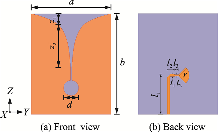
2 Analysis and ResultsThe Vivaldi antenna proposed in Ref.[14] is chosen as the element of the following arrays. As shown in Fig. 2 with a=20 mm, b=25.2 mm, d=3.8 mm, z1=11.4 mm, z2=2.8 mm, l1=10.05 mm, l2=1.8 mm, l3=1 mm, t1=0.6 mm, t2=0.28 mm, r=2.8 mm, the substrate thickness is 0.635 mm. The substrate thickness is 0.635 mm. The metal patch and the feeding structure are printed on each side of a FR-4 substrate. In the front view, the tapered slot line consists of two parts. The first part is determined by function y1(z)=0.14e0.27z(0 < z≤z1) and the second part is determined by function y2(z)=0.14e0.27z1e0.425(z-z1)(z1 < z≤z1+z2). In the back view, the fan-shaped feeding structure has a flare angle of 90°.Return loss of the antenna terminated with 50 Ω is given by simulation and experiment in Fig. 3, which are both less than -10 dB through the whole X-band and meets the engineering application requirement. The difference between simulated and measured results comes from the fact that the 50 Ω sub-miniature-A(SMA) is connected to the substrate by hand, which degrades the impedance match.
|
Fig. 2 Geometry of Vivaldi antenna |

|
Fig. 3 Return loss for the antenna shown in Fig. 2 |
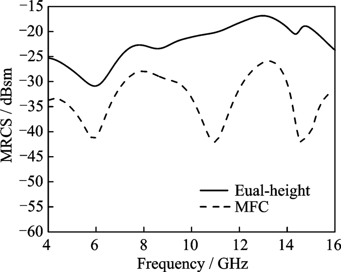
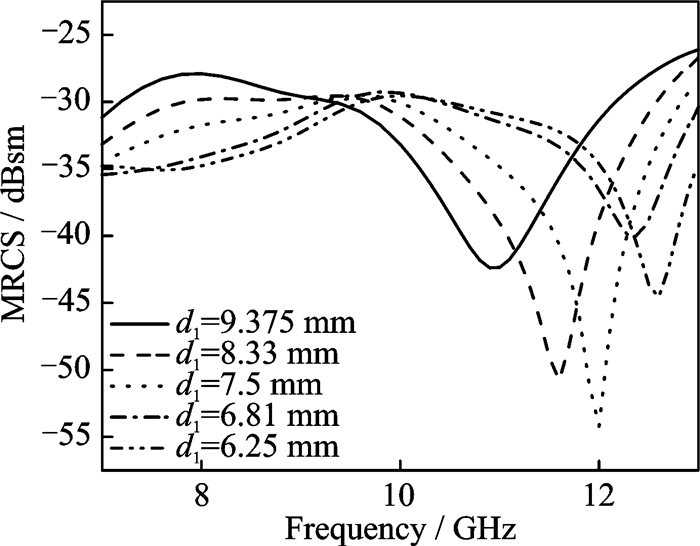
To understand the effect of MFC method, we consider a 1×4 Vivaldi antenna array as shown in Fig. 1. The distance between elements in X-direction is 21 mm which is 0.7 times the wavelength corresponding to 10 GHz. We set d1=9.375 mm, d2=6.25 mm, and d3=18.75 mm, which corresponds to a quarter wavelength at f1=8 GHz, f2=12 GHz, and f3=4 GHz, respectively. The large frequency space can help distinguish each cancellation point from the other. For a co-polarized incident wave in grazing angle, the monostatic radar cross section (MRCS) according to the frequency is shown in Fig. 4, and the MRCS of the conventional equal-height array is also given as reference. It can be observed from Fig. 4 that the MFC method produces considerable RCS reduction at 11, 14.6, and 6 GHz which contributes to low scattering performance over a wide frequency band. The three frequency points with the minimum MRCS are 2-3 GHz higher than the design due to the mutual coupling under asymmetric arrangement. This problem can be solved by optimization in practical designs. It can be seen in Fig. 5 that as d1 decreases from 9.375 mm to 6.25 mm while d2 and d3 remain unchanged, the cancellation frequency f1 increases from 11 GHz to 12.5 GHz accordingly. So, by optimizing di, we can shift fi to the desired frequency.
|
Fig. 4 MRCS of 1×4 array with equal-height arrangement and MFC arrangement |
|
Fig. 5 MRCS of 1×4 array with MFC for the case of different decrease from 9.375 mm to 6.25 mm in X-band |
It is worth noting that, in most cases, the frequency of detecting wave is unknown, which requires the antenna array to obtain low scattering performance over the whole operating band. Therefore, the average root mean square (RMS) value of RCS reduction can better reflect the overall effect of the stealth design method.
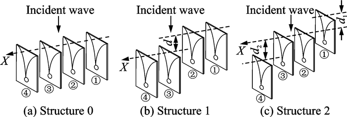
In order to achieve significant RCS reduction within X-band and compare the MFC method with the ladder arrangement method proposed in Ref.[13], the 1×4 Vivaldi antenna arrays of three different structures are studied, as shown in Fig. 6. Structure 0 represents the conventional equal-height arrangement and acts as reference. In Structure 1, we set d=8.33 mm, which involves only one cancellation frequency of 9 GHz. In Structure 2, we set d1=9.375 mm and d2=6.25 mm, Antennas 2 and 3 d1 lower than Antenna 1 and d2 higher than Antenna 4; i.e. Structure 2 represents the MFC employment of 8 and 12 GHz. The MRCS of above three structures is shown in Fig. 7. Results show that, on average, Structure 2 has almost 4 dB additional RCS reduction compared with that of structure 1 in the whole X-band. According to the radar function: Rmax4=PtG2δλ4/((4π)2S/N), the detection distance will decrease by 55% in Structure 1 and 64% in Structure 2, respectively.
|
Fig. 6 Geometry of 1×4 Vivaldi antenna array with equal-height arrangement, ladder arrangement and MFC |

|
Fig. 7 MRCS of 1×4 Vivaldi antenna array |
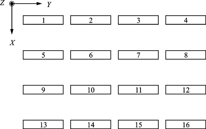
To further investigate the effect of MFC method on planar arrays, 4×4 Vivaldi antenna arrays of 5 different cases are discussed as follows. The distances between elements in X-direction and in Y-direction are both 21 mm. Overhead view of the array is shown in Fig. 8. Z-coordinates of elements in arrays of each case are given in Table 1, among which, di denotes a quarter wavelength of cancellation frequency fi. As we can see from Fig. 8 and Table 1, Case 0 represents the conventional planar arrays and acts as reference. Cases 1 and 2 comprise the cancellation structure at 10 GHz in two different ways. The MFC method is employed in Cases 3 and 4, where adjacent elements in X-direction comprise cancellation structure at f2 and in Y-direction at f3. In Case 3, f2 and f3 are assigned to 8 GHz and 12 GHz. In Case 4, f2and f3 are assigned to 9 GHz and 11 GHz.
|
Fig. 8 Overhead view of 4×4 arrays |
| Table 1 Z-coordinate of elements in 4×4 antenna arrays |
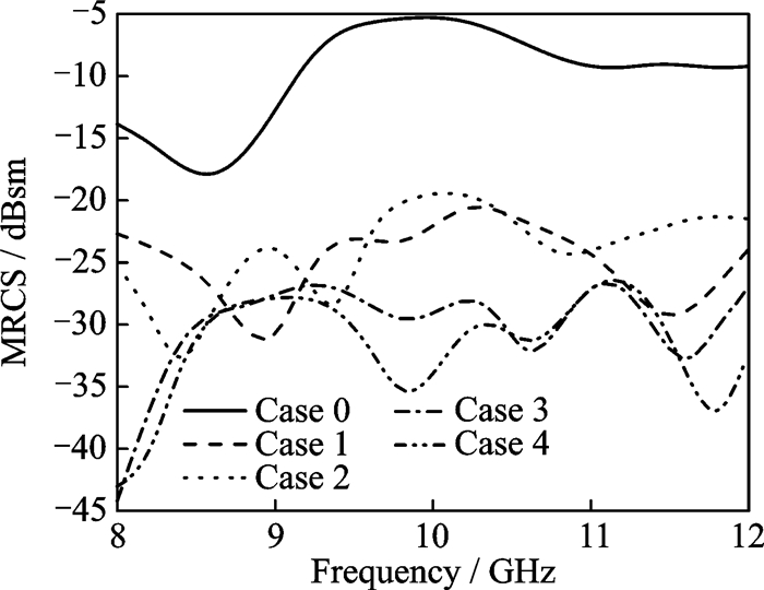
The MRCS of above 5 cases are shown in Fig. 9. The average RCS reductions in Cases 1-4 are given in Table 2. By comparison, Cases 3, 4 perform more than 5 dB additional RCS reduction than Cases 1, 2. As the MFC method increases the cancellation frequency points, Cases 3 and 4 have MRCS below -25 dB through the whole operating band. It is noted that, more antenna elements usually involve more cancellation structures, so the MFC method can be even more effective for the stealth design of middle- or large-scale antenna arrays.
|
Fig. 9 MRCS of 4×4 array in 5 cases |
| Table 2 Average RCS reduction in Cases 1-4 |
The MRCS in XOZ-plane in Cases 0, 3 and 4 are also investigated to study their scattering performance under oblique incident waves. It can be seen from Fig. 10 that, the back scattering of the antenna array in Cases 3, 4 is significantly reduced within ±60°. Similar low profile characteristic can be observed through the whole X-band.

|
Fig. 10 MRCS of 4×4 array in Cases 0, 3 and 4 for the incident wave ranging from -90° to +90° in XOZ-plane (f=10 GHz) |
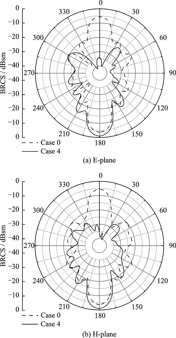
It is noteworthy that, as the total energy is not reduced by the MFC method, the reduction in RCS in a certain angle region will lead to the increase in RCS in other angle regions. We compare the bistatis radar cross section (BRCS) of Case 4 with that of Case 0. The co-polarized incident wave comes from Z-direction at 10 GHz.
As shown in Fig. 11, the main lobe of scattering in Case 4 is significantly reduced due to the cancellation while the back lobe arise. Fortunately, the strong scattering in back lobe is not in the threatening angle region, and it can be diminished by employing radar absorbing materials.
|
Fig. 11 BRCS of 10 GHz in Cases 0, 4 |
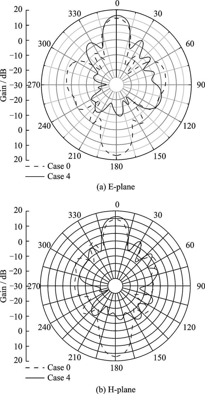
The simulated radiation pattern of Case 0 and Case 4 is given in Fig. 12. The phase differences of radiation wave between elements in Case 4 have been compensated in source. Results show that, the main lobe of radiation pattern has 2 dB enhancement but the side lobe has approximately 10 dB deterioration in E-plane. In addition, the back lobe is greatly reduced. In order to maintain the radiation performance, we set 90° phase difference between adjacent elements to compensate the phase difference caused by asymmetric arrangement. However, the compensation also leads to cancellation of radiation waves in back lobe direction for their 180° phase difference. In general, the antenna array keeps a favorable radiation pattern when employed with the MFC method.
|
Fig. 12 Radiation pattern of 10 GHz in Cases 0, 4 |
3 Conclusions
A stealth design method based on MFC for UWB end-fire antenna array is proposed. Vivaldi antenna arrays of different scales are discussed as examples to validate the effectiveness of the proposed method. Results show that the MFC method produces average 17.6 dB RCS reduction on 1×4 array and 22.6 dB RCS reduction on 4×4 array, and favorable radiation characteristics are maintained. By optimizing the Z-coordinate of each element properly, significant RCS reduction covering the whole operating band can be achieved. Therefore, the proposed method can be a good candidate for the stealth design of UWB end-fire antenna array.
Acknowledgement
This work was supported in part by Nanjing University of Aeronautics and Astronautics Research Funding (No.Kfjj20150414).
| [1] |
KNOTT F, SHAEFFER J F, TULEY M T. Radar cross section[M]. 2nd ed. Raleigh, NC: SciTech, 2004.
|
| [2] |
YANG H H, CAO X Y, ZHENG Q R, et al. Broadband RCS reduction of microstrip patch antenna using bandstop frequency selective surface[J]. Radioengineering, 2013, 22(4): 1275-1280. |
| [3] |
LI Y Q, ZHANG H, FU Y Q, et al. RCS reduction of ridged waveguide slot antenna array using EBG radar absorbing material[J]. IEEE Antennas and Wireless Propagation Letters, 2008, 7: 473-476. DOI:10.1109/LAWP.2008.2001548 |
| [4] |
ZHAO Y, CAO X Y, GAO J, et al. Broadband RCS reduction and high gain waveguide slot antenna with orthogonal array of polarisation-dependent AMC[J]. Electronics Letters, 2013, 49(21): 1312-1313. DOI:10.1049/el.2013.2417 |
| [5] |
ZHANG G Q, XU L M, CHEN A X. RCS reduction of Vivaldi antenna array using a PSS boundary[C]//Proceedings of the 8th International Symposium on Antennas Propagation and EM Theory (ISAPE'08). Kunming, China: [s.n.], 2008: 345-347.
|
| [6] |
LIU Y, GONG S X. A novel UWB clover-disc monopole antenna with RCS reduction[J]. Journal of Electromagnetic Waves & Applications, 2008, 22(8/9): 1115-1121. |
| [7] |
JIANG W, LIU Y, CONG S X, et al. Application of bionics in antenna radar cross section reduction[J]. IEEE Antennas and Wireless Propagation Letters, 2009, 8: 1275-1278. |
| [8] |
XUE J Y, LIU Y, WANG W, et al. A novel broadband bionic YAGI-UDA antenna with low radar cross section[C]//IET International Radar Conference 2013. Xi'an, China: IET, 2013: 1-4.
|
| [9] |
LI Y M, LIU H Y. RCS reduction of missile-borne quasi-traveling wave microstrip antenna[C]//20099th International Conference on Electronic Measurement & Instruments. Beijing, China: IEEE, 2009, 3: 246-249.
|
| [10] |
LI S J, CAO X Y, GAO J, et al. Fractal MA and for in-band RCS reduction of array antennas[C]//2015 IEEE International Wireless Symposium (IWS 2015). Shenzhen, China: IEEE, 2015: 1-4.
|
| [11] |
SEMENIKHIN A, SEMENIKHINA D V, YUKHANOV Y V. Control of RCS of cylindrical microstrip antenna array[C]//Proceedings ELMAR-2014. Zadar, Croatia: IEEE, 2014, 1(4): 227-230.
|
| [12] |
LU B, GONG S X, ZHANG S, et al. Optimum spatial arrangement of array elements for suppression of grating-lobes of radar cross section[J]. IEEE Antennas and Wireless Propagation Letters, 2010, 9: 114-117. |
| [13] |
CHEN T, LI W X, YAO Z H, et al. A novel stealth Vivaldi antenna[C]//Proceedings ICMMT. Shenzhen, China: IEEE, 2012, 3: 1-4.
|
| [14] |
HE X X, HUANG S S, CHEN T, et al. Ladder arrangement method for stealth design of Vivaldi antenna array[J]. International Journal of Antennas and Propagation, 2013, 2013(2): 1-7. |
 2018, Vol. 35


