2. Suzhou Automotive Research Institute, Tsinghua University (Wujiang), Suzhou 215200, P.R.China;
3. Key Laboratory of Advanced Manufacture Technology for Automobile Parts, Ministry of Education, Chongqing University of Technology, Chongqing 400054, P.R.China
With the continuous increase of the global car ownership, traffic safety has become the world matter of concern. Although more and more passive safety technologies, such as safety belts, airbags, energy absorption body and pedestrian protection, are applied to the vehicle to reduce the extent of damage in the accident, the primary cause of traffic accident has not been solved. Therefore, it promotes the development of advanced active safety technology, such as active collision avoidance system, adaptive cruise control system, and forward collision warning system.
The active collision avoidance system of the vehicle improves the perception of the intelligence system or the driver by sensors and modern communication technology. It collects the information of the car and environment, and judges the safety state of the vehicle according to the road condition, the driving habits etc. When the dangerous situation appears, the collision avoidance system will automatically take safety measures to prevent the occurrence of vehicle collisions and reduce the degree of accident injuries.
At present, the common strategy of active collision avoidance system is[1-2]: When the system estimates the vehicle in a dangerous situation, the control system will turn off the throttle and alert the driver to take corresponding operation. Otherwise, the system will automatically carry out the braking operation, and other related systems, such as ABS and ESP, may be employed together to ensure safe driving and avoid car crashes. However, such control strategy always makes the driver feel uncomfortable because of the emergency braking. Furthermore, it increases fuel consumption and reduces the road traffic efficiency.
However, the collision avoidance by steering can provide another method to bypass the obstacle and avoid crashes by controlling the vehicle's lateral movement[3-6].This method can provide a better obstacle avoidance trajectory by a path planner, and an appropriate path tracking control strategy is then adopted to make the car drive along the designed path. It not only can effectively decrease the incidence rate of collision accident caused by the driver's manipulation errors or emergency traffic situations, but also can promote the development of autonomous driving for intelligent vehicle in intelligent transportation in the future.
Consecutive curvity path is necessary to make the vehicle move smoothly along the designed trajectory. Otherwise, the vehicle needs to stop in the discrete curvature location and re-adjust the steering wheel angle, which is not desirable for the vehicle's smooth running. The trajectory planning based on parametric curve is a typical continuous method belonging to it, which contains B spline curve[7], β spline curve[8-9], polynomial functions[10] etc. B spline curve has the advantage of continuous curvature, and the one in the node of adjacent curve segment is also continuous, which makes it has the characteristics of strong applicability. If the constraint conditions of local trajectory are not satisfied, the corresponding control points can be revised by adjusting the corresponding control points, which does not affect the other segments. β spline curve is the extension and development of B spline curve. However, it makes the solution more complicated because of the added new parameters. The trajectory constructed by polynomial function also has the advantage of continuous curvature. This method needs to adjust the whole trajectory when the constraint conditions are not satisfied. Therefore, it leads to a large amount of calculation, and make its application restricted. In tracking control aspect, the published literatures always use an appropriate control method[11-14] to track the planned trajectory. Its control structure can be divided into direct control and hierarchical control. The direct control structure uses one controller to realize the vehicle dynamics control, and hierarchical control structure uses an upper controller and a lower controller to meet the complex design requirements. The upper controller computes the desired yaw rate and vehicle side slip angle according to the running environment, and makes the vehicle turn with the desired values. The lower controller controls the actuator to make the real value of the controlled variable consistent with the expected value. In this paper, we research the collision avoidance by proposing an alternative path planning and tracking control methods.
1 System ModelThe dynamics and inverse dynamics models of the collision avoidance system are established based on CarSim and MATLAB/Simulink software. The inverse dynamics model is generally used for receiving control signals and turning it into the signal which can be identified by the vehicle dynamics model. The dynamics model is used to simulate the real working condition of the vehicle, which receives the output information of the inverse dynamics model, and exports various state information in real time based on them.
1.1 Dynamic modelThe vehicle dynamics system is simplified to six subsystems of tire, suspension system, braking system, steering system, transmission system and aerodynamic system. The vehicle model is established based on D-Class, Seden model in Carsim software database, whose main parameters are shown in Table 1.
| Table 1 Main parameters of vehicle model |
For the convenience, the following assumptions are made when modeling:
(1) Selecting four wheel steering and no brake mode.
(2) Choosing the closed-loop shift control, and sixth mode of speed change.
(3) Setting the simulation time as 10 s, and no limit of the travel distance.
(4) Setting the simulation road as 3-D straight and flat road.
The angle transmission ratio of the steering system is not directly given in Carsim software. According to the dynamic curve of the steering system and the relation curve of steering system's output and left-right wheel angle, the angle transmission ratio is set as i=22.
The collision avoidance system needs to increase a sensor to detect the obstacle's information, which is transferred to the inverse dynamic model to generate the corresponding control signals. Therefore, the sensor and communication procedures are added to the in the test setup module, and the obstacle car is also set to it. The sensor is placed in the center of the car's front position, whose detection distance is set to 100 m, and the range of detection angle is [-45°, 45°]. The data collected by the sensor is automatic outputted to Simulink/Labview.
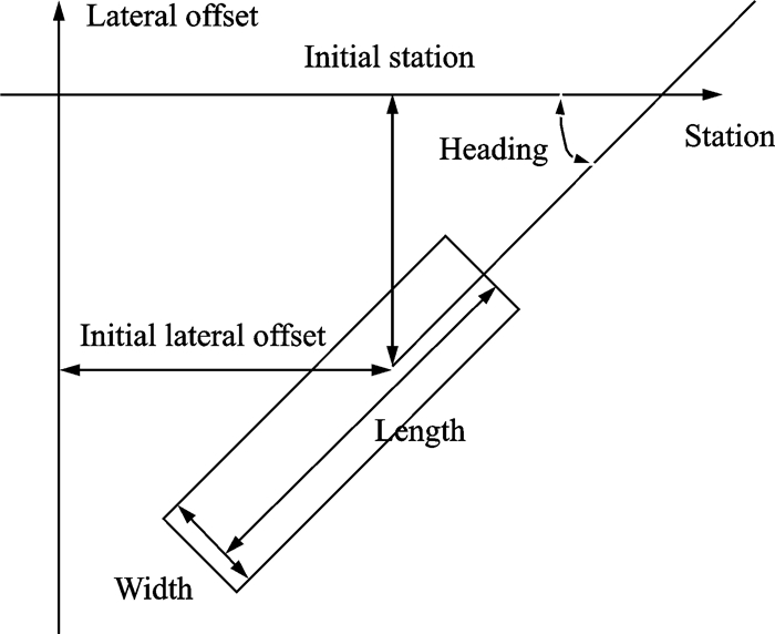
Fig. 1 shows the parameter setting interface of the obstacle car, which is located 150 m ahead in the control vehicle's way, and the heading angle is 0°. The speed of the static and moving obstacle car is set as 0 m/s and 5 m/s, respectively, and the controlled vehicle can avoid two kinds of obstacles under different conditions.
|
Fig. 1 Parameter setting interface of obstacle car |
1.2 Inverse dynamics model
The vehicle dynamic model has a strong nonlinearity. Thus, the inverse dynamic model is introduced to control it accurately. The inverse dynamic model can calculate the collision avoidance trajectory and steering angle based on output data of the sensor and Carsim, which is then fed back to the dynamic model to control the vehicle to follow the planning trajectory.
The uniform circular motion is a steady state response of the vehicle under step excitation of front wheel angle when it is moving at a constant velocity. In general, the steady-state yaw rate gain is used to evaluate its response quality. It can be expressed as
| $ \frac{{{\omega _{\rm{r}}}}}{\delta } = \frac{{u/L}}{{1 + K{u^2}}} $ | (1) |
| $ K = \frac{m}{{{L^2}}}\left( {\frac{a}{{{k_2}}} - \frac{b}{{{k_1}}}} \right) $ | (2) |
where K is the stability factor.
Taking
| $ {\delta _{{\rm{sw}}}} = {a_y}iL/{u^2} + {a_y}iLK $ | (3) |
where ay is the lateral acceleration, u the vehicle speed, i the angle transmission ratio of the steering system, L the wheelbase, and δsw the steering wheel angle.
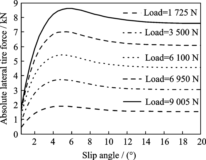
To determine K, the lateral stiffness k1 and k2 of the front and rear tire need to be obtained. We use the tire of 215/55R17 series, whose cornering characteristics curves under different loads given by Carsim software are shown in Fig. 2.
|
Fig. 2 Cornering characteristics of the tire under different loads |
Setting m=1 370 kg, a =l1=1.11 m, b= l2=1.666 m, then a single tire of front and rear wheel can be written as
| $ {F_1} = mg{l_2}/\left[ {2\left( {{l_1} + {l_2}} \right)} \right] = 4\;028.76\;{\rm{N}} $ | (4) |
| $ {F_2} = mg{l_1}/\left[ {2\left( {{l_1} + {l_2}} \right)} \right] = 2\;684.23\;{\rm{N}} $ | (5) |
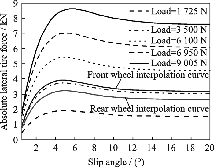
Making spline interpolation to the curve in Fig. 2, the interpolation curves of the front and rear tires can be obtained as shown in Fig. 3. Then, it is fitted by six degree polynomial, and the constant term obtained by the first derivative of the polynomial is the lateral stiffness under certain load.
| $ {k_1} = - 1.37 \times {10^5}{\rm{N/rad}} $ | (6) |
| $ {k_2} = - 1.08 \times {10^5}{\rm{N/rad}} $ | (7) |
|
Fig. 3 Interpolation curves of the front and rear tires |
To avoid an obstacles safely, a safety distance model is established to determine whether taking collision avoidance operation and trajectory planning. To simplify the problem, the whole process of collision avoidance is set to 3 s, and the coordinate origin is placed at the vehicle's centroid of mass in the beginning of the collision avoidance operation. The forward direction of the vehicle is x axis, and y axis is perpendicular to it and pointing to the collision avoidance trajectory. Furthermore, we only discuss the case of a single evasive goal of static or uniform motion in the controlled vehicle's way ahead.
The longitudinal speed of the vehicle is set as a fixed value, then the traveling distance s of the whole avoiding collision process in x-axis direction can be written as
| $ s = {v_{\rm{s}}} \times t $ | (8) |
Since too small safety distance between the controlled and obstacle vehicle at high speed may cause collision, the safety distance model should include the dynamic safety distance d. In this paper, d is set as 15 m (about 3 times of the car's length). For the uniform motion obstacles case, the safety distance should also be related to its speed. Because the longitudinal velocity of the vehicle is fixed, the safety distance can be determined by the relative speed of them. Thus, the safety distance P is determined as follows
| $ P = \left( {{v_{\rm{r}}} \times t + 15} \right)/2 $ | (9) |
After the safety distance model is determined, it is needed to put forward the judgment logic. The collision avoidance system works by judging the controlled automobile in danger conditions, thus, the judgment basis is as follows:
(1) The distance between the controlled and obstacle car is equal or less than the safety distance.
(2) The speed of the controlled car is greater than that of the obstacle.
2 Path PlanningFig. 4 shows the overall scheme of the path planning process for the collision avoidance system. The parameters of the vehicle, such as acceleration and speed, are measured by the sensors. The obstacle's information, such as relative velocity, obstacle's width, is obtained by the radar. The safety distance is calculated by the relative velocity of the controlled vehicle and obstacle. When it is judged to employ the conflict-free operation, the actuators immediately carries out the optimal path planning based on genetic algorithm (GA).

|
Fig. 4 Overall scheme of path planning process |
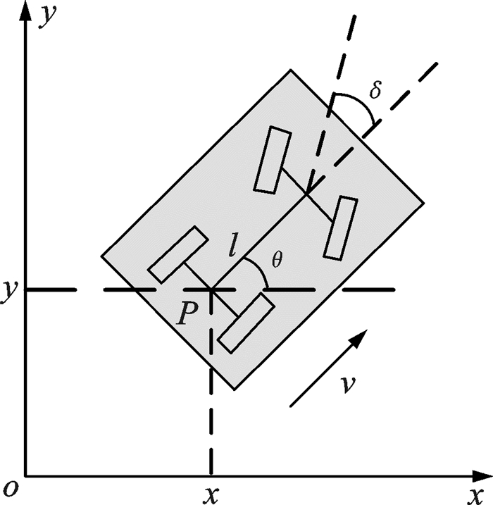
In the trajectory planning process, the obstacle vehicle is set to be static or moving at a constant speed, and the trajectory planning process is selected in double lane of 7 m width. The actual vehicle is simplified into the dynamic model shown as Fig. 5, where the reference point P(x, y) is the midpoint of automobile rear axle in the global coordinate system, θ the yaw angle, δ the front wheel angle, v the longitudinal speed of the vehicle, and l the wheelbase.
|
Fig. 5 Simplified vehicle model |
The vehicle's kinematic state can be expressed as[9]
| $ \dot x\left( t \right) = v\cos \theta \left( t \right) $ | (10) |
| $ \dot y\left( t \right) = v\sin \theta \left( t \right) $ | (11) |
| $ \dot \theta \left( t \right) = \frac{{v\tan \delta \left( t \right)}}{l} $ | (12) |
Fig. 6 shows the evasive scheme of the controlled vehicle in the collision avoidance process. Assuming that the controlled Vehicle A is traveling with the speed v0, it detects an obstacle Vehicle B with the speed v1 is travelling on its way (if the obstacle is static, v1=0). In order to avoid the collision between the two vehicles, the lateral operation is carried out by Vehicle A based on the path planner.

|
Fig. 6 Evasive scheme of the controlled vehicle |
The initial state of Vehicle A is set to
According to the initial and terminal state of the vehicle, the constraint equations can be written as follows
| $ \left\{ \begin{array}{l} f\left( {x,t} \right)\left| {_{{t_0}}} \right. = {x_0},f\left( {y,t} \right)\left| {_{{t_0}}} \right. = {y_0}\\ \dot f\left( {x,t} \right)\left| {_{{t_0}}} \right. = {{\dot x}_0},\dot f\left( {y,t} \right)\left| {_{{t_0}}} \right. = {{\dot y}_0}\\ \ddot f\left( {x,t} \right)\left| {_{{t_0}}} \right. = {{\ddot x}_0},\ddot f\left( {y,t} \right)\left| {_{{t_0}}} \right. = {{\ddot y}_0}\\ f\left( {x,t} \right)\left| {_{{t_{\rm{f}}}}} \right. = {x_{\rm{f}}},f\left( {y,t} \right)\left| {_{{t_{\rm{f}}}}} \right. = {y_{\rm{f}}}\\ \dot f\left( {x,t} \right)\left| {_{{t_{\rm{f}}}}} \right. = {{\dot x}_{\rm{f}}},\dot f\left( {y,t} \right)\left| {_{{t_{\rm{f}}}}} \right. = {{\dot y}_{\rm{f}}}\\ \ddot f\left( {x,t} \right)\left| {_{{t_{\rm{f}}}}} \right. = {{\ddot x}_{\rm{f}}},\ddot f\left( {y,t} \right)\left| {_{{t_{\rm{f}}}}} \right. = {{\ddot y}_{\rm{f}}} \end{array} \right. $ | (13) |
In Eq.(13), f(x, t) and (y, t) all have six constraints. Thus, parametric expression needs at least six free coefficients to meet these conditions. Meanwhile, more parameters are needed so as to obtain a feasible collision free path.
Therefore, the sixth order polyssnomials with seven coefficients are used to parameterize the collision avoidance trajectory, which can be expressed as
| $ \left\{ \begin{array}{l} f\left( {x,t} \right) = \sum\limits_{i = 0}^6 {{p_i}{t^i}} \\ f\left( {y,t} \right) = \sum\limits_{i = 0}^6 {{q_i}{t^i}} \end{array} \right. $ | (14) |
Taking Eq.(14) into Eq.(13), it can be obtained as
| $ \left\{ \begin{array}{l} {\mathit{\boldsymbol{H}}_1} = \mathit{\boldsymbol{LA + M}}{p_6}\\ {\mathit{\boldsymbol{H}}_2} = \mathit{\boldsymbol{LB + M}}{q_6} \end{array} \right. $ | (15) |
where
| $ \mathit{\boldsymbol{A}} = {\left[ {{p_0}\;{p_1}\;{p_2}\;{p_3}\;{p_4}\;{p_5}} \right]^{\rm{T}}} $ |
| $ \mathit{\boldsymbol{B}} = {\left[ {{q_0}\;{q_1}\;{q_2}\;{q_3}\;{q_4}\;{q_5}} \right]^{\rm{T}}} $ |
| $ {\mathit{\boldsymbol{H}}_1} = {\left[ {{x_0}\;{{\dot x}_0}\;{{\ddot x}_0}\;{y_0}\;{{\dot y}_0}\;{{\ddot y}_0}} \right]^{\rm{T}}} $ |
| $ {\mathit{\boldsymbol{H}}_2} = {\left[ {{x_{\rm{f}}}\;{{\dot x}_{\rm{f}}}\;{{\ddot x}_{\rm{f}}}\;{y_{\rm{f}}}\;{{\dot y}_{\rm{f}}}\;{{\ddot y}_{\rm{f}}}} \right]^{\rm{T}}} $ |
| $ \mathit{\boldsymbol{M}} = {\left[ {\begin{array}{*{20}{c}} {t_0^6}&{6t_0^5}&{30t_0^4}&{t_{\rm{f}}^6}&{6t_{\rm{f}}^5}&{30t_{\rm{f}}^4} \end{array}} \right]^{\rm{T}}} $ |
| $ \mathit{\boldsymbol{L}} = \left[ {\begin{array}{*{20}{c}} 1&{{t_0}}&{t_0^2}&{t_0^3}&{t_0^4}&{t_0^5}\\ 0&1&{2{t_0}}&{3t_0^2}&{4t_0^3}&{5t_0^4}\\ 0&0&2&{6{t_0}}&{12t_0^2}&{20t_0^3}\\ 1&{{t_{\rm{f}}}}&{t_{\rm{f}}^2}&{t_{\rm{f}}^3}&{t_{\rm{f}}^4}&{t_{\rm{f}}^5}\\ 0&1&{2{t_{\rm{f}}}}&{3t_{\rm{f}}^2}&{4t_{\rm{f}}^3}&{5t_{\rm{f}}^4}\\ 0&0&2&{6{t_{\rm{f}}}}&{12t_{\rm{f}}^2}&{20t_{\rm{f}}^3} \end{array}} \right] $ |
In Eq.(15), the p6 and q6 are uncertain, thus, the final planning trajectory is determined by these two parameters. In order to obtain the optimal paths with the minimum distance, the difference between the planning trajectory and the straight path needs to be reduced to the minimum. Furthermore, it also should guarantee the stability and ride comfort of the vehicle during the evasive process.
The objective function of the optimization is expressed as follows
| $ \begin{array}{*{20}{c}} {J\left( {f\left( {x,t} \right),f\left( {y,t} \right)} \right) = \int_{{t_0}}^{{t_{\rm{f}}}} {\left[ {{{\left( {f\left( {x,t} \right) - x'} \right)}^2} + } \right.} }\\ {\left. {{{\left( {f\left( {y,t} \right) - y'} \right)}^2}} \right]{\rm{d}}t + {{\left( {\max \_{{\ddot y}_{\rm{d}}}} \right)}^2}} \end{array} $ | (16) |
where (x′, y′) is the straight trajectory between s0 and sf; and max_
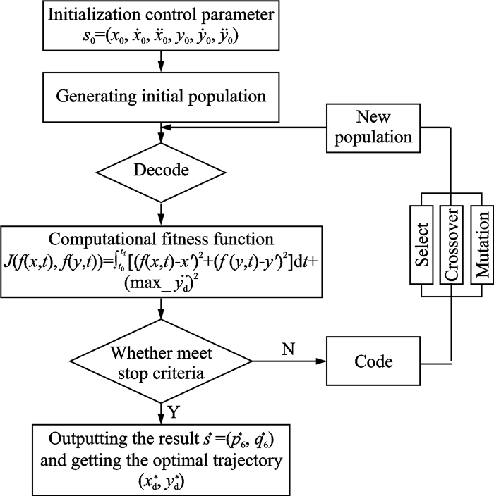
The planning trajectory is optimized by GA[15] to make the optimization objective
The flow chart of GA is shown in Fig. 7.
|
Fig. 7 Flow chart of GA |
3 Path Tracking Control
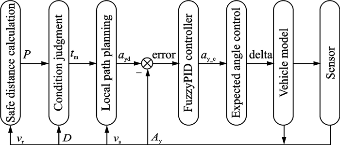
The overall scheme of path following control process for the collision avoidance system is shown in Fig. 8, where P is the calculated safety distance, D the distance between the controlled vehicle and the obstacle vehicle detected by sensors, vr the relative speed of the controlled and obstacle vehicle, vs the real-time speed, tm the start time of collision avoidance; ayd the expected lateral acceleration, Ay is the real-time lateral acceleration; ay_c the lateral acceleration by fuzzy PID controller, and deta the steering wheel angle obtained by ay_c.
|
Fig. 8 Overall scheme of path tracking control process |
The vehicle sensors collect the information of relative speed and distance between the controlled and the obstacle vehicle, which is used to calculate the real-time safety distance and judge the safety condition of the vehicle. When it is in dangerous state, the collision avoidance time is inputted to the path planning module immediately, and the local path planning is carried out. After calculating the desired lateral acceleration, the control variable of path tracking is obtained by fuzzy PID controller, which is then inputted to CarSim to make the vehicle drive along the optimal planning path.
We use the fuzzy PID controller with double inputs and three outputs. It takes the deviation e and deviation change rate ec of the ideal and actual lateral acceleration as the input variables, and the parameters Kp, Ki, Kd of the fuzzy PID controller as output variables.
The same membership functions are used to the input and output fuzzy sets, that is, beginning with Z type, middle part with triangle and latter end with S type. Fig. 9 shows the block diagram of fuzzy PID control.

|
Fig. 9 Block diagram of fuzzy PID control |
4 Simulation Results
In order to verify the control effect of the designed fuzzy PID controller, the simulation diagram of avoidance collision system is established based on Matlab/Simulink and CarSim software. When simulation, the speeds of the controlled vehicle are set to 80, 100, and 120 km/h, respectively, and obstacle vehicle is set to two state of stationary and uniform motion. The simulation results are compared with PID control method.
In the simulation, the controlled vehicle is set at the speed of 120 km/h to avoid the obstacle vehicle driving at a constant speed of 5 m/s. Fig. 10 shows the lateral displacement of the vehicle with collision avoidance system under different control methods. It can be seen from Fig. 10 that, compared with the desired trajectory, the maximum lateral displacement is smaller with no controller and PID controller, and there is time delay with the expected trajectory. However, the real-time trajectory under Fuzzy PID controller is consistent with the desired lateral displacement, and the time delay problem is also solved effectively.

|
Fig. 10 Lateral displacements of the vehicle under different controllers (v=120 km/h) |
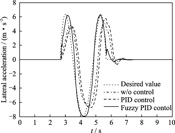
Fig. 11 shows the lateral acceleration of the controlled vehicle under different controllers. It can be seen from Fig. 11 that the amplitude of the actual lateral acceleration is smaller with no controller and PID controller, and there is obvious amplitude fluctuation after avoiding the obstacle vehicle. Further, its time delay is larger compared with the expected trajectory. However, under fuzzy PID controller, the amplitude of the actual lateral acceleration is in line with the expected one, and the amplitude fluctuation is small after avoiding collision. Therefore, the fuzzy PID controller has better control effect.
|
Fig. 11 Lateral acceleration of the vehicle under different controllers (v=120 km/h) |
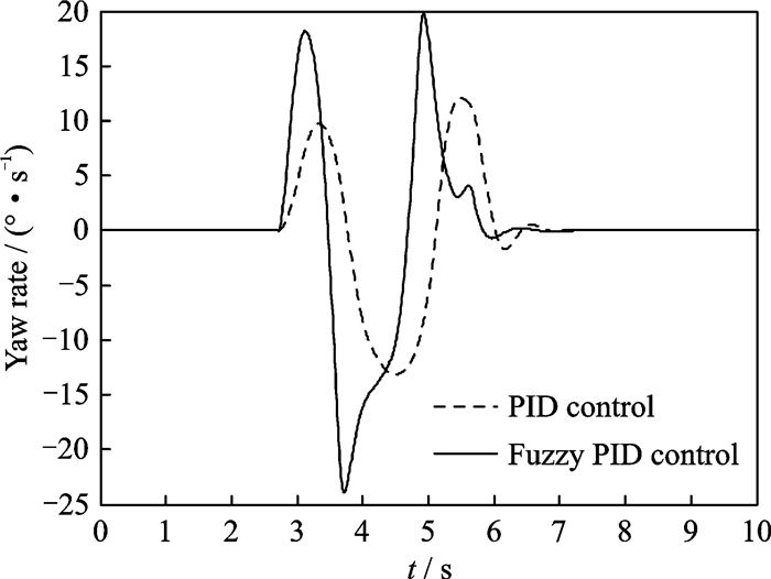
Fig. 12 shows the yaw rate response in the vehicle's collision process. Compared with PID controller, although the variation range of the yaw rate with fuzzy PID controller is larger, it is still in the reasonable range, and it can be rapidly stabilized with smaller amplitude. Therefore, the vehicle with fuzzy PID controller has good stability in the collision process, and it does not appear drastically swing.
|
Fig. 12 Yaw rate responses of the vehicle under different controllers (v=120 km/h) |
To sum up, in comparison with PID control, the control effect of fuzzy PID control is better in the speed of 120 km/h, the dynamic control parameters obtained by real-time deviation and deviation change rate can make the vehicle more accurately track the desired trajectory.
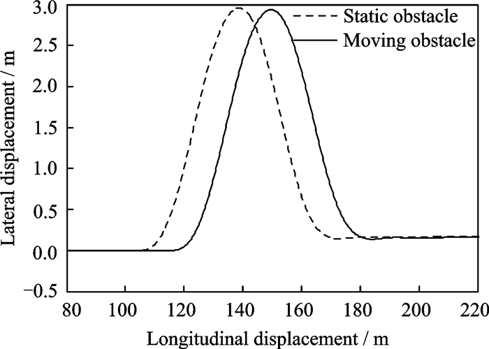
Fig. 13 shows the evasive trajectory of the controlled vehicle with the speed of 80 km/h to avoid the stationary and moving obstacles at a constant speed of 5 m/s, under fuzzy PID control. It can be seen from Fig. 13 that the lateral displacements under the two speeds are all the width of a lane, which is consistent with the designed situation. In addition, the longitudinal displacement is sufficient to avoid the static and constant motion obstacles, thus, the designed evasive trajectory is reasonable.
|
Fig. 13 Evasive trajectory under fuzzy PID control (v=80 km/h) |
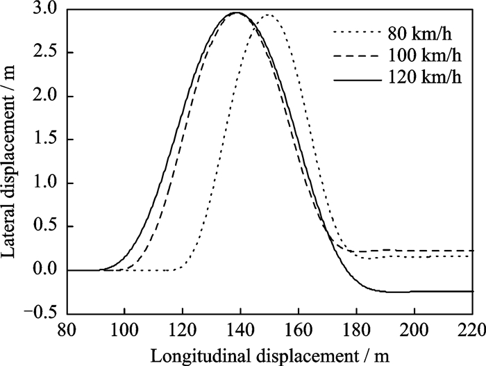
Fig. 14 shows the conflict-free trajectory of the controlled vehicle with the speeds of 80, 100, 120 km/h to avoid a moving obstacle at a speed of 5 m/s, under fuzzy PID control. It can be seen from Fig. 14 that the vehicle under three speeds is able to drive with a constant lateral displacement after the collision avoidance operation, which is consistent with the original driving intention. Therefore, the propoed path tracking controller can ensure the vehicle driving in accordance with the planned trajectory at different speeds.
|
Fig. 14 Evasive trajectories with fuzzy PID control at different speeds |
5 Conclusions
The dynamics and inverse dynamics model of the avoidance collision system based on Simulink and CarSim platform are established first. The obstacle vehicle is set to be static or moving at a constant speed, and sensors are added to detect the obstacle's information. The safety distance model is established according to the actual situation, which is used as the logic basis to start the implement of collision avoidance.
Then, the overall scheme of the path planning process for the collision avoidance system is worked out. Based on this, the local evasive trajectory is designed by polynomial parametric method. The coefficient of polynomial is determined by the vehicle's kinematic model and boundary conditions. Considering the stability of the vehicle in the conflict-free process, we take the minimum of the path planning and the target path as the optimization goal, and the designed planning trajectory is optimized by GA.
Finally, the overall scheme of path following control process is formulated. The path tracking control strategy of the collision avoidance system is researched based on fuzzy PID control method. In order to verify the path tracking effect, it is compared with the PID control method. Simulation results show that the vehicle with fuzzy PID controller has good stability in the collision process, and it can ensure the vehicle driving in accordance with the planned trajectory at different speeds.
AcknowledgementsThis work was supported by the National Key Research and Development Plan of China (No.2016YFB-0101102), the Suzhou Tsinghua Innovation Initiative (No.2016SZ0207), the National Natural Science Foundation of China (No.51375007), the Research Project of Key Laboratory of Advanced Manufacture Technology for Automobile Parts (Chongqing University of Technology), Ministry of Education (No.2015KLMT04), and the Fundamental Research Funds for the Central Universities (No. NE2016002).
| [1] |
DISTNER M, BENGTSSON M, BROBERG T, et al. City safety-A system addressing rear-end collisions at low speeds[C]//Proceedings 21st International Technical Conference on the Enhanced Safety of Vehicles.Sweden: [s.n.], 2009: 1-7.
|
| [2] |
GALVANI M, BIRAL F, NGUYEN B M, et al. Four wheel optimal autonomous steering for improving safety in emergency collision avoidance maneuvers[C]//2014 IEEE 13th International Workshop on Advanced Motion Control. Yokohama, Japan: IEEE, 2014: 362-367.
|
| [3] |
MOSHCHUK N, CHEN S K, ZAGORSKI C, et al. Optimal braking and steering control for active safety[C]//201215th International IEEE Conference on Intelligent Transportation Systems. Anchorage, Alaska, USA: IEEE, 2012, 2(1): 1741-1746. http://ieeexplore.ieee.org/xpls/abs_all.jsp?arnumber=6338640
|
| [4] |
BEVAN G, GOLLEE H, O'REILLY J. Automatic lateral emergency collision avoidance for a passenger car[J]. International Journal of Control, 2007, 80(11): 1751-1762. DOI:10.1080/00207170701324271 |
| [5] |
KIM J H, BIEN Z. A study on active collision avoidance system for the road vehicle[J]. Ieice Transactions on Information and Systems, 2001, 84(6): 717-726. |
| [6] |
CAO H T, SONG X L, HUANG Z Y, et al. Simulation research on emergency path planning of an active collision avoidance system combined with logitudinal control for an autonomous vehicle[J]. Journal of Automobile Engineering, 2016, 230(12): 1624-1653. DOI:10.1177/0954407015618533 |
| [7] |
DANIEL J, BIROUCHE A, LAUFFENBURGER J P, et al. Energy constrained trajectory generation for ADAS[C]//IEEE Intelligent Vehicle Symposium. USA: IEEE, 2010: 244-249. http://ieeexplore.ieee.org/xpls/icp.jsp?arnumber=5548110
|
| [8] |
PEI Y, WANG G Y, ZHANG Y. Microscopic model of automobile lane-changing virtual desire trajectory by spline curves[J]. Promet-Traffic & Transportation, 2010, 22(3): 203-208. |
| [9] |
GÁMEZ-BRAVOA F, CUESTAB F, OLLEROB A, et al. Continuous curvature path generation based on β-spline curves for parking manoeuvres[J]. Robotics and Autonomous Systems, 2008, 56(4): 360-372. DOI:10.1016/j.robot.2007.08.004 |
| [10] |
SHIM T, ADIREDDY G, YUAN H. Autonomous vehicle collision avoidance system using path planning and model-predictive-control-based active front steering and wheel torque control[J]. Proc IMechE Part D:J Automobile Engineering, 2012, 226(6): 767-778. DOI:10.1177/0954407011430275 |
| [11] |
SHAH J, BEST M, BENMIMOUN A, et al. Autonomous real-end collision avoidance using an electric power steering system[J]. Journal of Automobile Engineering, 2015, 229(12): 1638-1655. DOI:10.1177/0954407014567517 |
| [12] |
LIN C F, JYH C, LI K R. Active collision avoidance system for steering control of autonomous vehicles[J]. Iet Intelligent Transport Systems, 2014, 8(6): 550-557. DOI:10.1049/iet-its.2013.0056 |
| [13] |
LLORCA D F, MILANES V, ALONSO P I, et al. Autonomous pedestrian collision avoidance using a fuzzy steering controller[J]. IEEE Transactions on Intelligent Transportation Systems, 2011, 12(2): 390-401. DOI:10.1109/TITS.2010.2091272 |
| [14] |
CHANG K, XIA Y Q, HUANG K L, et al. Obstacle avoidance and active disturbance rejection control for a quadrotor[J]. Neurocomputing, 2016, 190: 60-69. DOI:10.1016/j.neucom.2016.01.033 |
| [15] |
MAHJOUBI H, BAHRAMI F, LUCAS C. Path planning in an environment with static and dynamic obstacles using genetic algorithm: A simplified search space approach[C]//2006 IEEE International Conference on Evolutionary Computation. Vancouver, BC, Canada: IEEE, 2006: 2483-2489.
|
 2018, Vol. 35


