2. Department of Mechanical Engineering, Texas A&M University, Texas 77843, USA;
3. Department of Aerospace Engineering, University of Michigan, MI 48109, USA
Despite the abundance of ambient vibrations, conventional linear rectilinear energy harvesters have notoriously limited efficiency[1], as they typically only work efficiently in a narrow band of frequencies centered around their own natural frequency, which reduces their power density. To widen the output bandwidth, active tuning mechanisms have been developed that adjust the natural frequency of the harvesters in response to the excitation frequency[2, 3]. Study on circuit design for energy harvesters using switching techniques to increase harvesting efficiency have also been done[4, 5]. For instance, the self-powered synchronized switching interface can extend the effective bandwidth by four times.
Another popular approach is to enable nonlinearity of the energy harvesters to obtain high-energy orbits by introducing external magnetic forces. The so-called nonlinear energy harvesters (NEHs), could be designed as softening or hardening configurations to widen output bandwidth under excitations with slowly varying frequen-cies[6]. Multiple cantilever beams with different but close natural frequencies have been also integrated to achieve broad bandwidth[7-9] but there is no interaction between these cantilever beams. To explore the interaction effect on the broadband output, two degree-of-freedom(2DOF) harvesters have been constructed[10-13] to have double resonant peaks and increased frequency bandwidth.
These aforementioned approaches can also be combined, such as using magnetic forces to couple two cantilever beams, and to form a nonlinear 2DOF energy harvester[14, 15]. Experimental investigation has shown a nearly 100% increase in the operating bandwidth and a 41% increase in the magnitude of the power output at an excitation level of 2 m/s2 [15]. Such nonlinear energy harvesters could make the resonant peaks commensurable with suitable parameters, which results in more resonant peaks and wider bandwidth. Experiments have demonstrated a 130% increase in the bandwidth in comparison to their linear counterparts at an excitation level of 2 m/s2 [16].
However, the efficiency of NEHs is still much lower than rotary generators[17]. Rotary generators, generally outperform rectilinear devices, owning to concentrated magnetic flux variation in the coil. While they are particularly well suited for low-frequency, large-amplitude oscillations, the application of rotary generators is restricted to purely rotational energy sources, e.g., wind turbines and hydroelectric stations.
A rectilinear-to-rotary motion conversion mechanism can address these shortcomings from both the rectilinear and the rotary nonlinear energy harvesters, and thus to provide an efficient approach to harvest low-frequency rectilinear vibrations. However, rectilinear-to-rotary motion conversion is traditionally achieved by using a combination of mechanical transmission components, such as crank and connecting rod or eccentric and pitman arm[18, 19]. Not withstanding their benefits, the complex mechanical transmission components required for coupling, and the introduced excessive volume, mass, wear, friction, and energy loss, present significant challenges to reliability and durability. In most of these aforementioned approaches, friction and inelastic deformation lead to significant energy loss.
This paper reports a contactless dual resonator for achieving high-power-density low frequency broadband energy harvesting, consisting of a rectilinear oscillator and a rotary oscillator coupled through magnetic forces.We derived the electromagnetic-dynamic governing equations of the nonlinear 2DOF system. The combination of restoring torques produced by the interaction of repulsive magnets and ferromagnetic screws with arc magnets can enable the dual resonances to be tuned for different vibration sources. Thus, a curve fitting model of the restoring torque under different configurations is developed for future simulation of the system. Furthermore, the experimental results for harvested power are presented to confirm the power harvesting capacity.
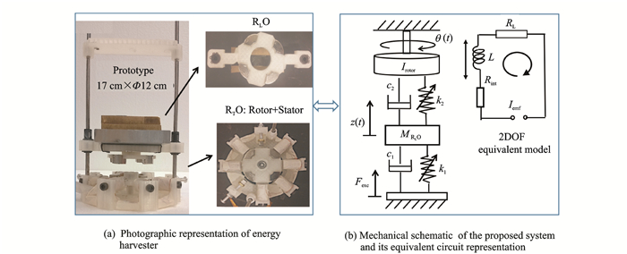
1 Structural DesignThe dual resonator (Fig. 1) builds off our previous work[20], consisting of a rectilinear oscillator (RLO) performing magnetic levitation and a rotary oscillator (RTO) performing electromagnetic coupling through a stator and a rotor. Both oscillators, coupled by magnetic forces generated by a set of arc permanent magnets (N52, 15 mm o.r. × 5 mm i.r. × 10 mm, 90°), radially magnetized and centro-symmetrically fixed onto the RLO and the rotor of the RTO achieve the reciprocating-to-rotary motion conversion and frequency up-conversion. Without the repulsive magnets, the magnetic interaction between the eight ferromagnetic screws and the rotor generates eight angular equilibrium positions (0, π/4, 2π/4, 3π/4, π, 5π/4, 6π/4 and 7π/4). Two repulsive rectangular magnets (8 mm×8 mm×8 mm) are attached in the stator in RTO (Fig. 1(a)) to reduce the number of equilibrium positions from eight to four, and to shallow the potential well. The stator also has six coils (2 000 turns, 50 Ω). For each coil, a ferromagnetic screw is inserted inside to increase the magnetic flux cross the coil and it generates magnetic interaction with the magnets on the rotor, which along with the two repulsive magnets creates the desired potential well distribution.
|
Fig. 1 Structural design and mechanical schematic |
The equivalent mechanical model of the harvester is presented schematically in Fig. 1(b). The governing equations of the nonlinear 2DOF system subjected to base excitation Fexc can be described by
| $ \left\{ \begin{array}{l} m\ddot z + {c_1}\dot z = {F_{{\rm{exc}}}} + F\left( {\theta, z} \right)-{F_{\rm{f}}}-mg\\ I\ddot \theta + \left( {{c_2} + \frac{{k_u^2\sin \left( {4\theta } \right)}}{{{R_{{\rm{int}}}} + {R_{\rm{L}}}}}} \right)\dot \theta = {M_{\rm{r}}}\left( \theta \right) + \tau \left( {\theta, z} \right)\\ {V_{{\rm{out}}}} = \frac{{{k_u}{R_{\rm{L}}}\sin \left( {4\theta } \right)\dot \theta }}{{{R_{{\rm{int}}}} + {R_{\rm{L}}}}} \end{array} \right. $ | (1) |
where z, m and c1 are the displacement, mass and damping coefficient of the RLO, respectively; Fexc the input excitation force; Ff the friction force on RLO from the steel shafts; θ, I and c2 the angular displacement, angular mass and damping coefficient of the RTO, respectively; ku the constant coefficient about electromechanical coupling; RL the load resistance; Rint the internal resistance of the harvester; Vout the output voltage caused by the varied electromagnetic field; F(θ, z) and τ(θ, z) the magnetic force and torque between the RLO magnet and the rotor magnets, and Mr the restoring torque generated by repulsive magnets and ferromagnetic screws on RTO.
Eq.(1) shows that the angular displacement and angular acceleration has significant effect on the output voltage. The functions of F(θ, z) and τ(θ, z) have been developed in our previous work[21]. In order to predict the response of the system, it becomes necessary to figure out how the restoring torque Mr produced by the interaction of arc magnets with repulsive magnets and attractive ferromagnetic screws result in a change in the rotational motion. So, the following section will derive the analytical model of the restoring torque on RTO.
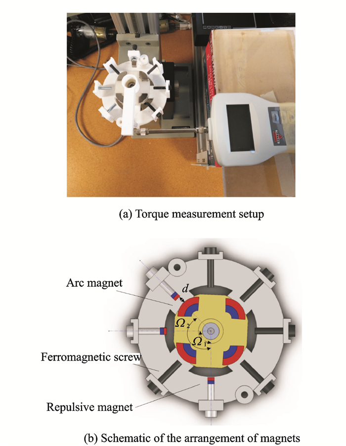
2 Restoring Torque of RTO: Parametric Study and Analysis 2.1 Experimental measurementThe restoring torque Mr was decided by the positions and quantities of repulsive magnets. To accurately describe the nonlinear characteristics of the energy harvester, the accurate nonlinear restoring torque Mr on rotor is needed. Since the size of arc magnets and repulsive magnets cannot be ignored compared with the distance between them, the Gilbert model[22] or the Ampère model[23] which assumes the permanent magnet as either a magnetic charge or magnetic dipole is not suitable for the system. Therefore, curve fitting method was used to derive the expression of Mr acted on the rotor from measurement data. As shown in Fig. 2, the stator of the rotary oscillator was fixed to a platform. By adjusting the side knob, the platform could rotate a certain angle. One end of a bar was fixed to the center of rotor, another end to the tip of the force sensor. The force corresponding to the angle can be read by the force sensor. By multiplying the force and the distance, the torque Mr could be calculated. d is the normal distances from the surface of repulsive magnets to the outer surface of the RTO magnets. Ω is the angle between two repulsive magnets.
|
Fig. 2 Experimental setup of restoring torque measurement |
2.2 Modeling and systematic analysis
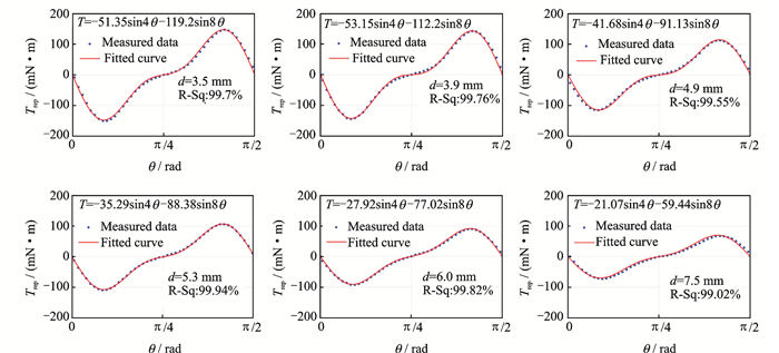
The restoring torque Mr measured at any point on the RTO is a combination of torques generated by the interaction of repulsive magnets (Trep) and arc magnets as well as attractive ferromagnetic screw (Tscr) and arc magnets. These torques are superimposed on each other. First, the repulsive torque function (Trep) at different distance d when only one repulsive magnet was attached is needed to obtain. The torques at d=3.5, 3.9, 4.9, 5.3, 6.0 and 7.5 mm were measured and plotted in Fig. 3. Curve fitting was used to characterize the nonlinear restoring torque. The common function of the torque can be expressed as
|
Fig. 3 Restoring torques when only one magnet was applied at different distances(Trep) |
| $ {T_{{\rm{rep}}}}\left( \theta \right) = A\sin \left( {4\theta } \right) + B\sin \left( {8\theta } \right) $ | (2) |
with different coefficients A and B, which are dependent on the distance d.
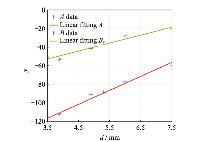
By linear fitting A and B, as shown in Fig. 4, we have
|
Fig. 4 Linear fitting of coefficients A and B |
| $ \left\{ \begin{array}{l} A\left( d \right) = 15.04d-169.19\\ B\left( d \right) = 8.552\;4d-82.74 \end{array} \right. $ | (3) |
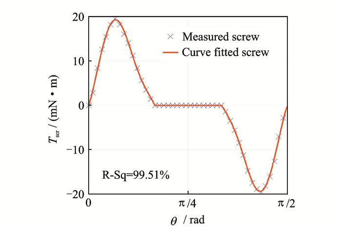
The same procedure was conducted to measure the torque produced by one attractive ferromagnetic screw, experimental result and curve fitted is shown in Fig. 5.
|
Fig. 5 Curve fitted of torque given by ferromagnetic screw (Tscr) |
Thus, the equation of torque (Tscr) can be expressed as the following equations in one period (π/2)
| $ \left\{ {\begin{array}{*{20}{l}} {{T_{{\rm{scr}}}}\left( \theta \right) = 16.7\sin \left( {5.875\theta + 0.1572} \right) + 3.018\sin \left( {15.665\theta- 1.402} \right)}&{\theta \in \left[{0, \frac{{\rm{ \mathsf{ π} }}}{6}} \right]}\\ {{T_{{\rm{scr}}}}\left( \theta \right) = 0}&{\theta \in {\rm{Other}}\;{\rm{values}}}\\ {{T_{{\rm{scr}}}}\left( \theta \right) = 16.7\sin \left( {5.875\theta + 3.189} \right) + 3.018\sin \left( {15.665\theta + 2.056} \right)}&{\theta \in k\left[{\frac{{\rm{ \mathsf{ π} }}}{3}, \frac{{\rm{ \mathsf{ π} }}}{2}} \right]} \end{array}} \right. $ | (4) |
The comprehensive restoring torque Mr is the combination of torques generated by repulsive magnets and ferromagnetic screws, which gives
| $ {M_r}\left( \theta \right) = \sum {{T_{{\rm{rep}}}}} \left( i \right) + {T_{{\rm{scr}}}}\left( j \right)\;\;\;\;i + j = 8 $ | (5) |
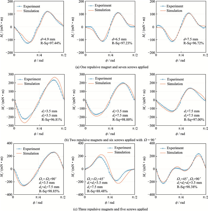
Simulated the torque for different configurations of repulsive magnets by using equation Mr, as shown in Fig. 6, the simulation results agree well with the experimental results no matter the number of repulsive magnets or varied distance d were applied demonstrating the validity of our fitted equations.
|
Fig. 6 Experimental and simulation results of the restoring torque (Mr) |
In this section, we created a systematic model of the restoring torque (Mr), whose waveform has approximated sinusoidal dependence on the rotor angular displacement. By adding the repulsive magnets, the number of equilibrium positions can be reduced from 8 to 4, that is, the period of restoring torque changes with the presence of repulsive magnet(s): π/4 without magnet and π/2 with magnet, respectively. Through experimental verification, the curve fitting model can accurately describe the restoring torque of RTO under different repulsive magnets configurations, which will benefit for predicting the response of the dual resonator system.
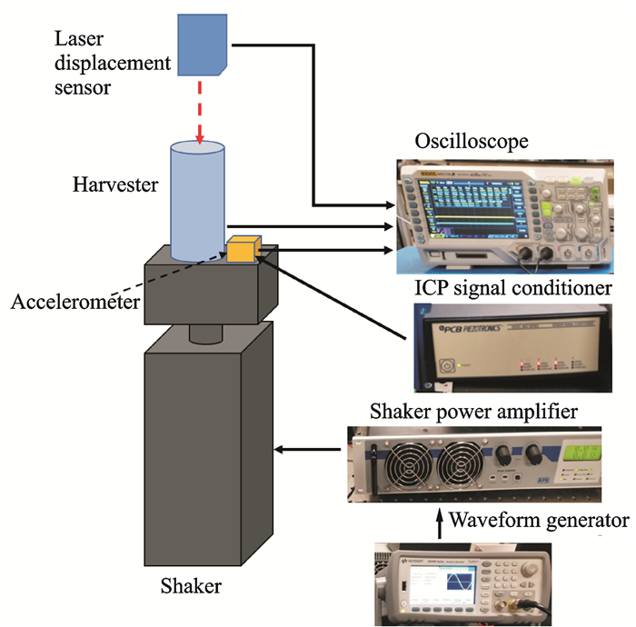
3 Power Output AnalysisTo illustrate the behavior of the energy harvester, excite this system at different frequency to move the RLO upward or downward the RTO, thereby producing a repulsive torque to push the rotor oscillate at a certain degree and then the rotor will swing back due to the potential energy well. As shown in Fig. 7, a long stroke electrodynamic shaker (APS dynamics Inc.) is controlled by a signal generator (KEYSIGHT 33500B) in conjunction with a power amplifier (APS 125) to provide a sine excitation with various frequencies acted on the prototype harvester. A piezo accelerometer (PCB333B32) measures the input excitation level and a laser sensor (optoNCDT1402, Micro-Epsilon Inc.) measures the rectilinear displacement of the RLO.
|
Fig. 7 Schematic diagram of the experimental setup |
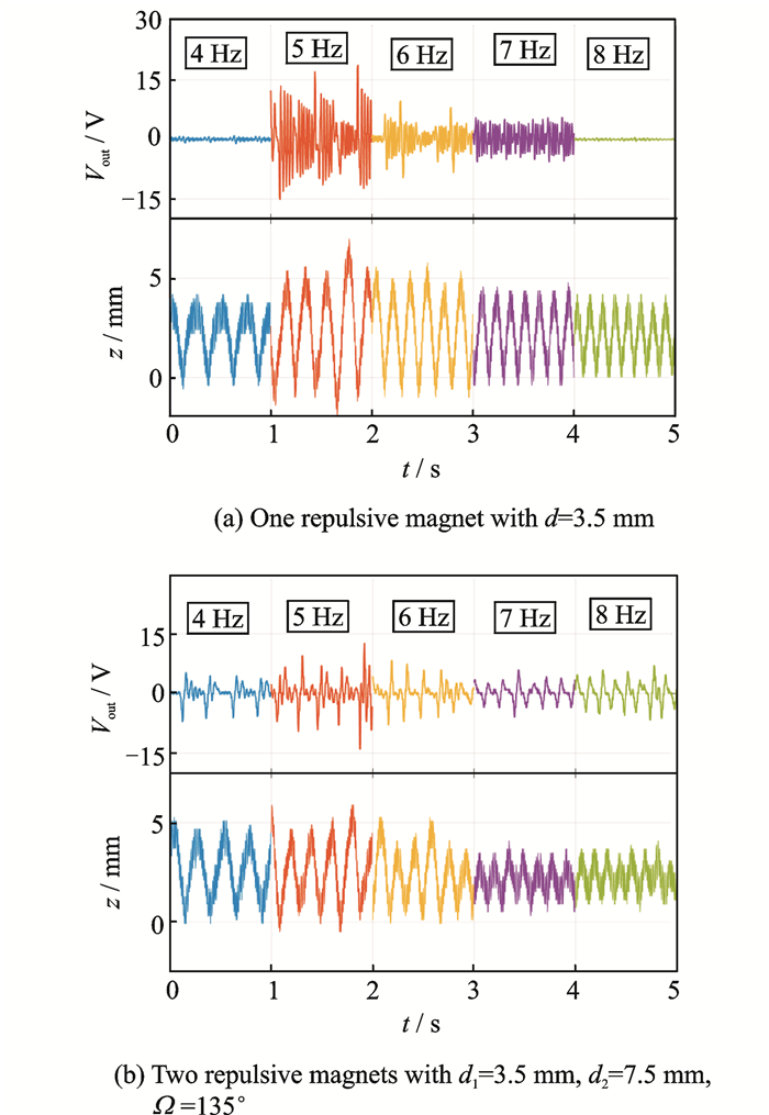
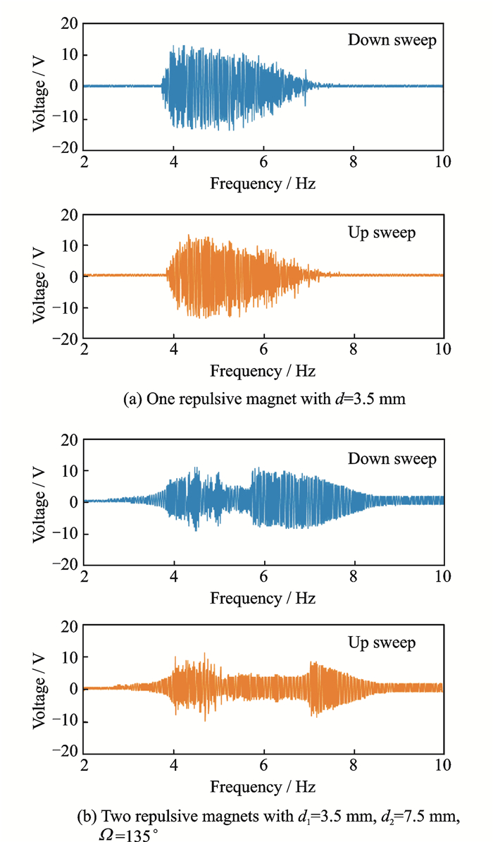
Fig. 8 shows the time history plot of the open-circuit voltage and corresponding RLO displacement at different with one repulsive magnets (d=3.5 mm), Fig. 8(a), and two repulsive magnets (d1=3.5 vmm, d2=7.5 mm, Ω=135°), Fig. 8(b), attached. One magnet has a higher and denser voltage output than two magnets due to the larger restoring torque which result in a deeper potential energy well. However, the shallow potential energy well (two magnets) results in a wider bandwidth. For one magnet configuration, it was also found that with input excitations being at low frequencies, the driving magnet might get stuck and does not pluck the rotor effectively. With a higher input frequency (5—7 Hz), the RLO is able to drive the rotor to escape potential energy wells with a high angular velocity. The rotor oscillates over equilibrium positions for several vibration cycles periodically and generates output voltage at larger amplitude. However, when the input frequency is larger than 7 Hz, due to the small amplitude rectilinear motion, the RLO does not have strong magnetic interaction with the rotor. Therefore, the output voltage is small. The frequency-up conversion is observed when the RLO drives the rotor to escape potential wells, and the subsequent driving torque starts to deflect the rotor before the resonant vibration induced by the previous torque had fully run down.
|
Fig. 8 Experimental output voltage and RLO displacement under different input frequencies and 0.5g acceleration |
Fig. 9 shows the frequency responses of the open circuit voltage against excitation frequencies ranged from 2 Hz to 10 Hz under 0.5g base accelerations. One repulsive magnet configuration has a denser output voltage and most voltages are achieved at 4—7.5 Hz range. Two repulsive magnets configuration has a wider operation bandwidth from 4 Hz to 8 Hz.
|
Fig. 9 Frequency sweep of output voltage at 0.5g acceleration |
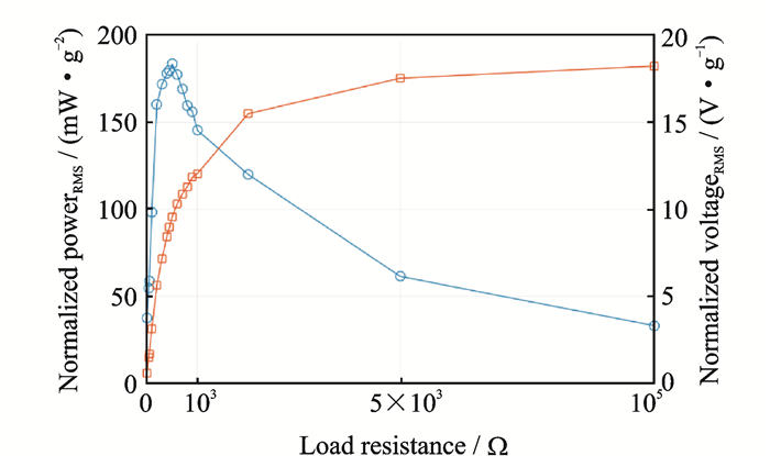
A tunable resistor was connected between the electrodes of the harvester to experimentally determine the optimal load-resistance for maximum power output when one repulsive magnets (d=3.5 mm) was attached. The value RL of the resistor and voltage VR across the load were measured. The instantaneous power delivered by the energy harvester can be obtained according to P=VR2/RL. Fig. 10 shows the experimental results of output RMS power and RMS voltage, normalized by the base acceleration, versus load resistance. The maximum output RMS power is 183 m W/g2at the resistive load of 500 Ω, which is three times larger than our previous work.
|
Fig. 10 Experimental measurement of RMS power output and RMS voltage output under harmonic excitation of 5 Hz at 0.5g |
4 Conclusions
This paper reports a contactless high-power-density energy harvester energy was harvested using coils and magnets by converting stochastic reciprocating motion into controllable rotation, to provide intrinsic frequency up-conversion, and to be configured into specific applications to obtain and maintain high-energy obits of multi-stable energy harvesting with near-unity energy conversion efficiency and bandwidth widening. A parametric study is also presented to underlie the dynamic mechanisms of the prototype, a curve fitting model of restoring torque was developed, and a reliable approach is proposed to estimate the magnetic interaction for given configurations, which can be used for predicting response of the electromechanical system. The experiment power analysis demonstrated the up-conversion of a 5 Hz input excitation into an output voltage with a frequency of about 30 Hz, which is six times the input frequency. The maximum output RMS power is 183 mW/g2 at the resistive load of 500 Ω, which is three times larger than our previous work.
Acknowledgements
This work was partially supported by the U.S. Office of Navy Research (No.N000141410230), and partially supported by the Department of Energy ARPA-E (No.DOE-AR0000531).
| [1] |
DENG W, WANG Y. Input-dependent performance study of a nonlinear piezoelectric energy harvester[J]. Journal of Intelligent Material Systems and Structures, 2016. DOI:10.1177/0123456789123456 |
| [2] |
LELAND E S, WRIGHT P K. Resonance tuning of piezoelectric vibration energy scavenging generators using compressive axial preload[J]. Smart Materials and Structures, 2006, 15(5): 1413. DOI:10.1088/0964-1726/15/5/030 |
| [3] |
CHALLA V R, PRASAD M, SHI Y, et al. A vibration energy harvesting device with bidirectional resonance frequency tunability[J]. Smart Materials and Structures, 2008, 17(1): 015035. DOI:10.1088/0964-1726/17/01/015035 |
| [4] |
SHIH Y S, VASIC D, WU W J. A non-contact mechanical solution for implementing synchronized switching techniques for energy harvesting using reed switches[J]. Smart Materials and Structures, 2016, 25(12): 125013. DOI:10.1088/0964-1726/25/12/125013 |
| [5] |
LALLART M. Nonlinear technique and self-powered circuit for efficient piezoelectric energy harvesting under unloaded cases[J]. Energy Conversion and Management, 2017, 133: 444. DOI:10.1016/j.enconman.2016.10.065 |
| [6] |
STANTON S C, MCGEHEE C C, MANN B P. Reversible hysteresis for broadband magnetopiezoelastic energy harvesting[J]. Applied Physics, 2009, 95(17): 174103. |
| [7] |
SHAHRUZ S. Design of mechanical band-pass filters for energy scavenging[J]. Journal of Sound and Vibration, 2006, 292(3): 987. |
| [8] |
FERRARI M, FERRARI V, GUIZZETTI M, et al. Piezoelectric multifrequency energy converter for power harvesting in autonomous microsystems[J]. Sensors and Actuators A: Physical, 2008, 142(1): 329. DOI:10.1016/j.sna.2007.07.004 |
| [9] |
XUE H, HU Y, WANG Q M. Broadband piezoelectric energy harvesting devices using multiple bimorphs with different operating frequencies[J]. Ultrasonics, Ferroelectrics, and Frequency Control, IEEE Transactions on, 2008, 55(9): 2104. DOI:10.1109/TUFFC.903 |
| [10] |
ZHOU W, PENAMALLI G R, ZUO L. An efficient vibration energy harvester with a multi-mode dynamic magnifier[J]. Smart Materials and Structures, 2011, 21(1): 015014. |
| [11] |
ALADWANI A, ARAFA M, ALDRAIHEM O, et al. Cantilevered piezoelectric energy harvester with a dynamic magnifier[J]. Journal of Vibration and Acoustics, 2011, 134(3): 031004. |
| [12] |
KIM I, JUNG H, LEE B M S. Broadband energy-harvesting using a two degree-of-freedom vibrating body[J]. Applied Physics Letters, 2011, 98(21): 214102. DOI:10.1063/1.3595278 |
| [13] |
CHEN S J, WU J Y. Fabrication of a 2-DoF electromagnetic energy harvester with in-phase vibrational bandwidth broadening[J]. Smart Materials and Structures, 2016, 25(9): 095047. DOI:10.1088/0964-1726/25/9/095047 |
| [14] |
ZHOU S, CAO J, WANG W, et al. Modeling and experimental verification of doubly nonlinear magnet-coupled piezoelectric energy harvesting from ambient vibration[J]. Smart Materials and Structures, 2015, 24(5): 055008. DOI:10.1088/0964-1726/24/5/055008 |
| [15] |
TANG L, YANG Y. A nonlinear piezoelectric energy harvester with magnetic oscillator[J]. Applied Physics Letters, 2012, 101(9): 094102. DOI:10.1063/1.4748794 |
| [16] |
XIONG L, TANG L, MACE B R. Internal resonance with commensurability induced by an auxiliary oscillator for broadband energy harvesting[J]. Applied Physics Letters, 2016, 108(20): 203901. DOI:10.1063/1.4949557 |
| [17] |
DENG W, WANG Y. Low frequency energy harvesting with contactless-coupled rectilinear-rotary oscillations mediated by magnetic interaction towards frequency up-conversion and wider bandwidth[J]. Applied Physics Letters, 2012(101): 094102. |
| [18] |
DENG W, WANG Y. Apparatus and method for harvesting electromagnetic energy from low frequency vibration using rectilinear oscillator coupled to rotary counterpart: US62376169[P]. 2016.
|
| [19] |
DENIJS J F, Lindner M. Transmission for converting rotary motion into linear motion: US5690567 A[P]. 1997.
|
| [20] |
BAUER F. Device for converting rectilinear motion into rotary motion: US3279269 A[P]. 1966.
|
| [21] |
DENG W, WANG Y. Non-contact magnetically coupled rectilinear-rotary oscillations to exploit low frequency broadband energy harvesting with frequency up-conversion[J]. Applied Physics Letters, 2016, 109(14): 133903. |
| [22] |
DENG W, WANG Y. A dual resonant rectilinear-to-rotary oscillation converter for low frequency broadband electromagnetic energy harvesting[J]. Smart Materials and Structures, 2017, 26(9): 095059. DOI:10.1088/1361-665X/aa721f |
| [23] |
AKOUN G, YONNET J P. 3D analytical calculation of the forces exerted between two cuboidal magnets[J]. IEEE Transactions on Magnetics, 1984, 20(5): 1962-1964. DOI:10.1109/TMAG.1984.1063554 |
| [24] |
YUNG K W, LANDECKER P B, VILLANI D D. An analytic solution for the force between two magnetic dipoles[J]. Magnetic and Electrical Separation, 1998, 9(1): 39-52. DOI:10.1155/1998/79537 |
 2018, Vol. 35


