In some cases dry friction is disadvantageous in mechanical systems, such as in rubbing faults of rotor systems[1-4]. However, dry friction has been widely used to increase the stability of mechanical systems, such as the dry friction damping blade of aero-engines and turbines[5-8].
In order to restrain the vibration of rotor system, series of measures have been taken by researchers, such as magnetorheological fluid damper and dry friction damper[9-10]. It has been proved theoretically and experimentally that the elastic support/dry friction damper can significantly attenuate the vibration amplitude of a rotor system in the critical speed region[11-14]. Fan proposed that friction damping could be applied in rotor system[12]. He designed an elastic support/dry friction damper using a spring to provide the pressing force and experimentally studied the damping performance of this damper. The experimental results showed a great damping performance. Based on his work, Wang Siji designed an active elastic support/dry friction damper using an electro-magnetic actuator, which can conveniently be actively controlled by adjusting the control voltage of the electromagnet[15-17]. For different conditions, this active damper can be operated under different control strategies. Wang Siji also studied its performance of the damper for some rotor faults such as a crack in the elastic support, sudden blade-out event and unstable vibration of the rotor and found that this damper has a good damping effect[18-21].
For theoretical study of the elastic support/dry friction damper, only a simple mechanism model was established in which the rotor was simplified to a single-degree-of-freedom system or a two-degree-of-freedom system, and the classic one-dimensional hysteretic dry friction model was used[12]. This type of analysis model was sufficient for illustrating the friction damping mechanism of the dry friction damper, but it is limited and insufficient for the next study on the damping performance with variable design parameters. The limitation is mainly reflected in the following two points: (1) The axial location of the damper influences the damping performance of the elastic support/dry friction damper, which cannot be studied in the current analysis model. (2) The relative motion between the friction pair is a two-dimensional motion, which is considered one-dimensionally in the current analysis model.
In this paper, a two-dimensional friction model-ball/plate model based on the classic one-dimensional hysteretic dry friction model is proposed. By using the ball/plate model, a rotordynamic model for rotordynamic analysis of a rotor with elastic support/dry friction dampers was established and experimentally verified. Finally, the damping performance with respect to some variable parameters has been studied numerically, laying the foundation for the dynamic design of the elastic support/dry friction damper.
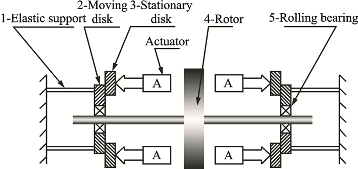
1 Basic Operation PrinciplesFig. 1 shows the basic operation principles of a rotor with elastic support/dry friction dampers. The rotor is supported by two elastic supports, and at the end cross section of each one, the dry friction damper is affixed. Each damper consists of three key components: The elastic support, the friction pairs (stationary disk and moving disk) and the actuator. The elastic supports redistribute the strain energy of the whole rotor-support system and concentrate the vibration, which is then dissipated by the dry friction between the friction pairs. The moving disk, which is fixed to the end cross section of the elastic support, is connected to the bearing outer ring and vibrates with the elastic support but does not rotate with the rotor. The stationary disk is fixed to the casing and can be moved in the axial direction by the actuator. The frictional force between the two disks can be changed by adjusting the pressing force from the actuator. So the actuator is the core component of the damper.
|
Fig. 1 Basic operation principles of the elastic support/dry friction damper |
If the moving disk fixed to the end cross section of the elastic support vibrates with the rotor vibration, a relative motion between the moving disk and the stationary disk will take place. When the actuator provides an appropriate pressing force, this will lead to dry friction damping dissipating the vibration energy.
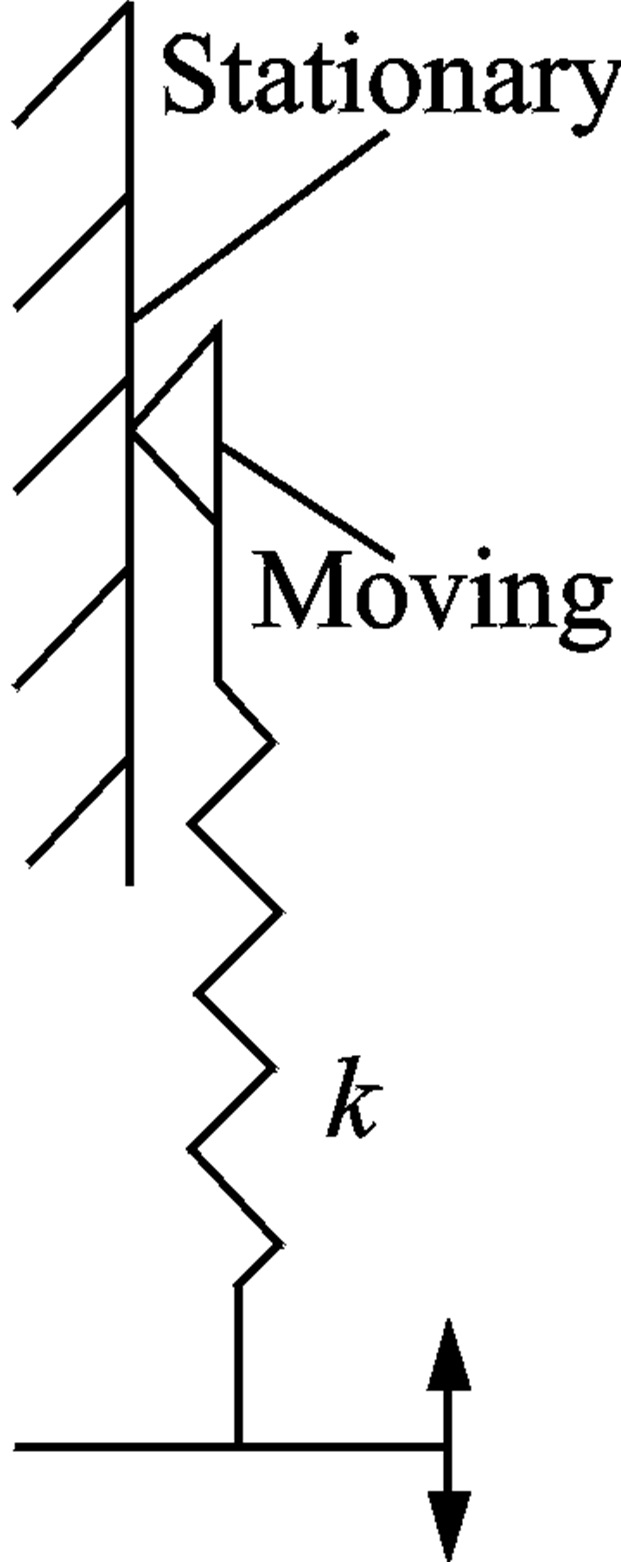
2 Rotordynamic Modeling 2.1 Friction modelFan and Wang[12, 16] studied the elastic support/dry friction damper on a rotor by using the hysteretic dry friction model shown in Fig. 2, where k is the stiffness of the contact interface.
|
Fig. 2 Hysteretic dry friction model |
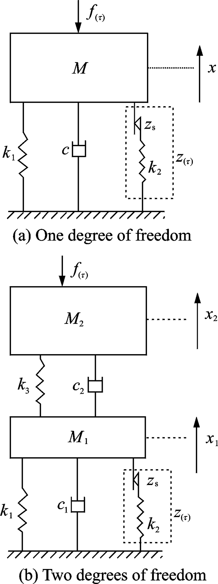
The whole rotor system with dampers was simplified as a mass-spring system shown in Fig. 3, where M is the equivalent mass, k the equivalent stiffness, c the equivalent damp, f(τ) the load on the system, and x and z represent the displacement. The basic characteristics of the damper can be explained by this simplified model. However, for further study, this simplified model is inadequate.
|
Fig. 3 Simplified model of a rotor system with an elastic support/dry friction damper[12] |
The inadequacy of the model in Fig. 2 is that in a rotor system, a two-dimensional translation may occur between the moving disk and the stationary disk, and the friction force may be a circumferential force, but in the model in Fig. 2, only one-dimensional motion was considered. The rotor model in Fig. 3 was oversimplified for further study of the dynamics.
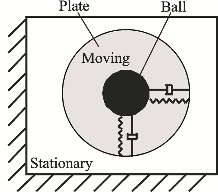
Based on the above considerations, a two-dimensional friction model-ball/plate model (shown in Fig. 4) is proposed. This ball/plate model was developed from the hysteretic dry friction model, and it is clear and simple to describe the rotor system with elastic support/dry friction dampers.
|
Fig. 4 Ball/plate dry friction model |
As shown in Fig. 4, in the ball/plate dry friction model, the stationary disk is represented by a rectangle. The moving disk consists of a ball and a plate. The plate (without considering its mass) represents the contact interface between the moving disk and the stationary disk, and the ball represents the moving disk. The ball and the plate are connected with ideal springs and linear damping in two directions. The ideal springs represent the tangential contact stiffness of the contact interface. The displacement between the ball and the plate represents the microscopic sliding in the state of static friction. So if the applied force on the ball is greater than maximum static friction, the ball will touch the edge of the plate, and the plate will begin to move.
Both the stationary disk and the moving disk have two degrees of freedom in the ball/plate dry friction model. When the stationary disk is fixed, its displacement remains zero in each degree of freedom. But when there is a stiffness between the stationary disk and ground, the displacement will depend on the friction force of the contact interface.
The ball/plate dry friction model is actually a type of two-dimensional hysteretic dry friction model. The frictional force between the stationary disk and the plate is Coulomb′s friction force. The frictional force at any time depends on the motion state of the plate and the applied force with which the ball acts on the plate.
Without considering the mass of the plate, the resultant force acting on the plate will be 0 at any time. When the plate is stationary relative to the stationary disk, namely the friction pair is in the state of static friction, the frictional force acting on the plate is
| $ {F_{\rm{f}}} = - \left[ {k\left( {{r_1} - {r_2}} \right) + d\left( {{{\dot r}_1} - 0} \right)} \right] < \mu N $ | (1) |
If
| $ {F_{\rm{f}}} = - \frac{{{{\dot r}_2} - {{\dot r}_{\rm{j}}}}}{{\left| {{{\dot r}_2} - {{\dot r}_{\rm{j}}}} \right|}}\mu N $ | (2) |
In Eqs.(1, 2): r1=x1+iy1 is the displacement of the ball; r2=x2+iy2 is the displacement of the plate; rj=xj+iyj is the displacement of the stationary disk, its value is 0 when the stationary disk remains at rest; k is the stiffness coefficient between the ball and the plate; d is the damping coefficient between the ball and the plate; μ is the friction coefficient; and N is the pressing force.
By mechanical analysis of this two-dimensional friction model, the motion equations of the friction pair can be established conveniently.
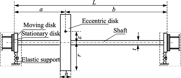
2.2 Rotor systemA single-disk flexible rotor with elastic support/dry friction dampers is shown in Fig. 5. The system consists of two parts: A rotor and two elastic support/dry friction dampers (in the dashed boxes). The rotor is a single offset disk with a flexible shaft that is supported by two elastic supports at both ends. The two elastic support/dry friction dampers can be set up at each elastic support, shown in the dashed boxes of Fig. 5. In Fig. 5, L is the length between the two supports; a is the length between the left support and the rotor disk; b is the length between the right support and the rotor disk; r is the diameter of the rotor disk; ε is the eccentricity of the rotor disk; t is the diameter of the shaft.
|
Fig. 5 A single-disk flexible rotor with elastic support/dry friction dampers |
For the rotor disk, four coordinates are required to describe its motion. Two of them (x, y) describe its two-dimensional translation; the other two (φx, φy) describe its two-dimensional swing. For the left friction pair, based on Section 2.1, six coordinates are required to describe the two-dimensional motion of the moving disk (the ball and the plate) and the stationary disk: xb1 and yb1 describe the motion of the ball; xd1 and yd1 describe the motion of the plate; and xj1 and yj1 describe the motion of the stationary disk. In the same way, another six coordinates describe the motion of the right friction pair. They are xb2, yb2, xd2, yd2, xj2, yj2. So in total, the whole rotor system is a system with 16 degrees of freedom (16-DOF system).
2.3 Motion equationsBy means of Euler′s laws of motion, the motion equations of the rotor disk, moving disk and stationary disk can be obtained as follows.
The rotor disk
| $ \begin{array}{*{20}{c}} {m\mathit{\boldsymbol{\ddot r}} + {s_{11}}\mathit{\boldsymbol{r}} - i{s_{12}}\mathit{\boldsymbol{\varphi }} - \left( {\frac{{L - a}}{L}{s_{11}} + \frac{1}{L}{s_{12}}} \right){\mathit{\boldsymbol{r}}_{{\rm{b1}}}} - }\\ {\left( {\frac{a}{L}{s_{11}} - \frac{1}{L}{s_{12}}} \right){\mathit{\boldsymbol{r}}_{12}} = m\varepsilon {\mathit{\Omega }^2}{{\rm{e}}^{{\rm{i}}\mathit{\Omega }t}}} \end{array} $ | (3) |
| $ \begin{array}{*{20}{c}} {{J_{\rm{d}}}\mathit{\boldsymbol{\ddot \varphi }} - j{J_{\rm{p}}}\mathit{\Omega }\mathit{\boldsymbol{\dot \varphi }} + {\rm{i}}{s_{21}}\mathit{\boldsymbol{r}} + {s_{22}}\mathit{\boldsymbol{\varphi }} - {\rm{i}}\left( {\frac{{L - a}}{L}{s_{21}} + } \right.}\\ {\left. {\frac{1}{L}{s_{22}}} \right){\mathit{\boldsymbol{r}}_{{\rm{b1}}}} - {\rm{i}}\left( {\frac{a}{L}{s_{21}} - \frac{1}{L}{s_{22}}} \right){\mathit{\boldsymbol{r}}_{{\rm{b2}}}} = 0} \end{array} $ | (4) |
The moving disk (the ball in the ball/plate model)
| $ \begin{array}{*{20}{c}} {{m_{{\rm{b1}}}}{{\mathit{\boldsymbol{\ddot r}}}_{{\rm{b1}}}} + \left( {{d_{{\rm{b1}}}} + d} \right){{\mathit{\boldsymbol{\dot r}}}_{{\rm{b1}}}} + {A_1}\mathit{\boldsymbol{r}} + {A_2}\mathit{\boldsymbol{\varphi }} + {A_3}{\mathit{\boldsymbol{r}}_{{\rm{b1}}}} + }\\ {{A_4}{\mathit{\boldsymbol{r}}_{{\rm{b2}}}} = k{\mathit{\boldsymbol{r}}_{{\rm{d1}}}} + \dot d{\mathit{\boldsymbol{r}}_{{\rm{d1}}}}} \end{array} $ | (5) |
where
| $ \left\{ \begin{array}{l} {A_1} = - \left( {\frac{{L - a}}{L}{s_{11}} + \frac{1}{L}{s_{21}}} \right)\\ {A_2} = {\rm{i}}\left( {\frac{{L - a}}{L}{s_{12}} + \frac{1}{L}{s_{22}}} \right)\\ {A_3} = {\left( {\frac{{L - a}}{L}} \right)^2}{s_{11}} + \frac{{L - a}}{{{L^2}}}{s_{21}} + \\ \;\;\;\;\;\;\;\frac{{L - a}}{{{L^2}}}{s_{12}} + \frac{1}{{{L^2}}}{s_{22}} + \left( {{s_{{\rm{bl}}}} + k} \right)\\ {A_4} = \frac{{\left( {L - a} \right)a}}{{{L^2}}}{s_{11}} + \frac{a}{{{L^2}}}{s_{21}} - \\ \;\;\;\;\;\;\;\frac{{L - a}}{{{L^2}}}{s_{12}} - \frac{1}{{{L^2}}}{s_{22}} \end{array} \right. $ |
| $ \begin{array}{*{20}{c}} {{m_{{\rm{b2}}}}{{\mathit{\boldsymbol{\ddot r}}}_{{\rm{b2}}}} + \left( {{d_{{\rm{b2}}}} + d} \right){{\mathit{\boldsymbol{\dot r}}}_{{\rm{b2}}}} + {B_1}\mathit{\boldsymbol{r}} + {B_2}\mathit{\boldsymbol{\varphi }} + {B_3}{\mathit{\boldsymbol{r}}_{{\rm{b1}}}} + }\\ {{B_4}{\mathit{\boldsymbol{r}}_{{\rm{b2}}}} = k{\mathit{\boldsymbol{r}}_{{\rm{d2}}}} + \dot d{\mathit{\boldsymbol{r}}_{{\rm{d2}}}}} \end{array} $ | (6) |
where
| $ \left\{ \begin{array}{l} {B_1} = - \left( {\frac{a}{L}{s_{11}} - \frac{1}{L}{s_{21}}} \right)\\ {B_2} = {\rm{i}}\left( {\frac{a}{L}{s_{12}} - \frac{1}{L}{s_{22}}} \right)\\ {B_3} = \frac{{\left( {L - a} \right)a}}{{{L^2}}}{s_{11}} - \frac{{L - a}}{{{L^2}}}{s_{21}} + \frac{a}{{{L^2}}}{s_{12}} - \frac{1}{{{L^2}}}{s_{22}}\\ {B_4} = {\left( {\frac{a}{L}} \right)^2}{s_{11}} - \frac{a}{{{L^2}}}{s_{21}} - \frac{a}{{{L^2}}}{s_{12}} + \frac{1}{{{L^2}}}{s_{22}} + \left( {{s_{{\rm{b2}}}} + k} \right) \end{array} \right. $ |
The stationary disk is
| $ {m_{{\rm{j1}}}}{{\mathit{\boldsymbol{\ddot r}}}_{{\rm{j1}}}} + {d_{{\rm{j1}}}}{{\mathit{\boldsymbol{\dot r}}}_{{\rm{j1}}}} - d{{\mathit{\boldsymbol{\dot r}}}_{{\rm{b1}}}} - k{\mathit{\boldsymbol{r}}_{{\rm{b1}}}} + {s_{{\rm{j1}}}}{\mathit{\boldsymbol{r}}_{{\rm{j1}}}} = - k{\mathit{\boldsymbol{r}}_{{\rm{d1}}}} - d{{\mathit{\boldsymbol{\dot r}}}_{{\rm{d1}}}} $ | (7) |
| $ {m_{{\rm{j2}}}}{{\mathit{\boldsymbol{\ddot r}}}_{{\rm{j2}}}} + {d_{{\rm{j2}}}}{{\mathit{\boldsymbol{\dot r}}}_{{\rm{j2}}}} - d{{\mathit{\boldsymbol{\dot r}}}_{{\rm{b2}}}} - k{\mathit{\boldsymbol{r}}_{{\rm{b2}}}} + {s_{{\rm{j2}}}}{\mathit{\boldsymbol{r}}_{{\rm{j2}}}} = - k{\mathit{\boldsymbol{r}}_{{\rm{d2}}}} - d{{\mathit{\boldsymbol{\dot r}}}_{{\rm{d2}}}} $ | (8) |
The plate of the moving disk is Eqs.(9, 10) (the plate in the ball/plate model).
| $ {{\mathit{\boldsymbol{\dot r}}}_{{\rm{d1}}}} = \left\{ \begin{array}{l} {{\mathit{\boldsymbol{\dot r}}}_{{\rm{j1}}}}\;\;\;\;\;\;\left| {k\left( {{\mathit{\boldsymbol{r}}_{{\rm{b1}}}} - {\mathit{\boldsymbol{r}}_{{\rm{d1}}}}} \right) + d\left( {{{\mathit{\boldsymbol{\dot r}}}_{{\rm{b1}}}} - {{\mathit{\boldsymbol{\dot r}}}_{{\rm{j1}}}}} \right)} \right| < \mu {N_1}\\ {{\mathit{\boldsymbol{\dot r}}}_{{\rm{b1}}}} - \left[ {\frac{{\mu {N_1}}}{d}\frac{{k\left( {{\mathit{\boldsymbol{r}}_{{\rm{b1}}}} - {\mathit{\boldsymbol{r}}_{{\rm{d1}}}}} \right) + d\left( {{{\mathit{\boldsymbol{\dot r}}}_{{\rm{b1}}}} - {{\mathit{\boldsymbol{\dot r}}}_{{\rm{j1}}}}} \right)}}{{\left| {k\left( {{\mathit{\boldsymbol{r}}_{{\rm{b1}}}} - {\mathit{\boldsymbol{r}}_{{\rm{d1}}}}} \right) + d\left( {{{\mathit{\boldsymbol{\dot r}}}_{{\rm{b1}}}} - {{\mathit{\boldsymbol{\dot r}}}_{{\rm{j1}}}}} \right)} \right|}} - } \right.\\ \;\;\;\;\;\;\left. {\frac{k}{d}\left( {{\mathit{\boldsymbol{r}}_{{\rm{b1}}}} - {\mathit{\boldsymbol{r}}_{{\rm{d1}}}}} \right)} \right]\\ \;\;\;\;\;\;\;\left| {k\left( {{\mathit{\boldsymbol{r}}_{{\rm{b1}}}} - {\mathit{\boldsymbol{r}}_{{\rm{d1}}}}} \right) + d\left( {{{\mathit{\boldsymbol{\dot r}}}_{{\rm{b1}}}} - {{\mathit{\boldsymbol{\dot r}}}_{{\rm{j1}}}}} \right)} \right| \ge \mu {N_1} \end{array} \right. $ | (9) |
| $ {{\mathit{\boldsymbol{\dot r}}}_{{\rm{d2}}}} = \left\{ \begin{array}{l} {{\mathit{\boldsymbol{\dot r}}}_{{\rm{j2}}}}\;\;\;\;\;\;\left| {k\left( {{\mathit{\boldsymbol{r}}_{{\rm{b2}}}} - {\mathit{\boldsymbol{r}}_{{\rm{d2}}}}} \right) + d\left( {{{\mathit{\boldsymbol{\dot r}}}_{{\rm{b2}}}} - {{\mathit{\boldsymbol{\dot r}}}_{{\rm{j2}}}}} \right)} \right| < \mu {N_2}\\ {{\mathit{\boldsymbol{\dot r}}}_{{\rm{b2}}}} - \left[ {\frac{{\mu {N_2}}}{d}\frac{{k\left( {{\mathit{\boldsymbol{r}}_{{\rm{b2}}}} - {\mathit{\boldsymbol{r}}_{{\rm{d2}}}}} \right) + d\left( {{{\mathit{\boldsymbol{\dot r}}}_{{\rm{b2}}}} - {{\mathit{\boldsymbol{\dot r}}}_{{\rm{j2}}}}} \right)}}{{\left| {k\left( {{\mathit{\boldsymbol{r}}_{{\rm{b2}}}} - {\mathit{\boldsymbol{r}}_{{\rm{d2}}}}} \right) + d\left( {{{\mathit{\boldsymbol{\dot r}}}_{{\rm{b2}}}} - {{\mathit{\boldsymbol{\dot r}}}_{{\rm{j2}}}}} \right)} \right|}} - } \right.\\ \;\;\;\;\;\;\left. {\frac{k}{d}\left( {{\mathit{\boldsymbol{r}}_{{\rm{b2}}}} - {\mathit{\boldsymbol{r}}_{{\rm{d2}}}}} \right)} \right]\\ \;\;\;\;\;\;\;\left| {k\left( {{\mathit{\boldsymbol{r}}_{{\rm{b2}}}} - {\mathit{\boldsymbol{r}}_{{\rm{d2}}}}} \right) + d\left( {{{\mathit{\boldsymbol{\dot r}}}_{{\rm{b2}}}} - {{\mathit{\boldsymbol{\dot r}}}_{{\rm{j2}}}}} \right)} \right| \ge \mu {N_2} \end{array} \right. $ | (10) |
In Eqs.(3-10), r = x + iy is the displacement of the rotor disk; φ = φx + iφy is the swing angle of the rotor disk; rb1 = xb1 + iygbg1 is the displacement of the left moving disk; rb2 = xb2 + iyb2 is the displacement of the right moving disk; rd1 = xd1 + iyd1 is the displacement of the left plate of the moving disk; rd2 = xd2 + iyd2 is the displacement of the right plate of the moving disk; rj1 = xj1 + iyj1 is the displacement of the left stationary disk; rj2 = xj2 + iyj2 is the displacement of the right stationary disk; m, mb1, mb2, mj1, and mj2 represent the masses of the rotor disk, the moving disks and the stationary disks, respectively; s11, s12, s21 and s22 represent the stiffness coefficients of the shaft at the rotor disk, where s11 is the displacement stiffness, s22 the angle stiffness, s12 and s21 are cross stiffness; sb1, sb2, sj1, and sj2 represent the stiffness coefficients of the elastic support and the stationary disk respectively; db1, db2, dj1, and dj2 represent the damping coefficients of the elastic support and the stationary disk, respectively; Jp and Jd respectively represent the polar moment of inertia and the moment of inertia about a diameter of the rotor disk; N1 and N2 represent the pressing force between the moving disk and stationary disk of the two dampers; k and d are the tangential contact stiffness coefficient and damping coefficient of the contact interface introduced by the ball/plate model; and Ω is the rotational speed of the rotor.
To solve the equations by numerical methods, the following variables are introduced
| $ \left\{ \begin{array}{l} {\mathit{\boldsymbol{u}}_1} = {\left\{ {\mathit{\boldsymbol{r}},\mathit{\boldsymbol{\varphi }},{\mathit{\boldsymbol{r}}_{{\rm{b1}}}},{\mathit{\boldsymbol{r}}_{{\rm{b2}}}},{\mathit{\boldsymbol{r}}_{{\rm{j1}}}},{\mathit{\boldsymbol{r}}_{{\rm{j2}}}}} \right\}^{\rm{T}}}\\ {\mathit{\boldsymbol{u}}_2} = {{\mathit{\boldsymbol{\dot u}}}_1}\\ {\mathit{\boldsymbol{u}}_3} = {\left\{ {{\mathit{\boldsymbol{r}}_{{\rm{d1}}}},{\mathit{\boldsymbol{r}}_{{\rm{d2}}}}} \right\}^{\rm{T}}} \end{array} \right. $ | (11) |
Eqs.(3-10) can be written in the following form
| $ \begin{array}{*{20}{c}} {\left[ {\begin{array}{*{20}{c}} \mathit{\boldsymbol{E}}&\mathit{\boldsymbol{O}}&\mathit{\boldsymbol{O}}\\ \mathit{\boldsymbol{O}}&\mathit{\boldsymbol{M}}&\mathit{\boldsymbol{O}}\\ \mathit{\boldsymbol{O}}&\mathit{\boldsymbol{O}}&\mathit{\boldsymbol{E}} \end{array}} \right]\left\{ {\begin{array}{*{20}{c}} {{{\mathit{\boldsymbol{\dot u}}}_1}}\\ {{{\mathit{\boldsymbol{\dot u}}}_2}}\\ {{{\mathit{\boldsymbol{\dot u}}}_3}} \end{array}} \right\} + \left[ {\begin{array}{*{20}{c}} \mathit{\boldsymbol{O}}&{ - \mathit{\boldsymbol{E}}}&\mathit{\boldsymbol{O}}\\ \mathit{\boldsymbol{S}}&\mathit{\boldsymbol{D}}&\mathit{\boldsymbol{O}}\\ \mathit{\boldsymbol{O}}&\mathit{\boldsymbol{O}}&\mathit{\boldsymbol{O}} \end{array}} \right]\left\{ {\begin{array}{*{20}{c}} {{\mathit{\boldsymbol{u}}_1}}\\ {{\mathit{\boldsymbol{u}}_2}}\\ {{\mathit{\boldsymbol{u}}_3}} \end{array}} \right\} = }\\ {\left\{ {\begin{array}{*{20}{c}} \mathit{\boldsymbol{O}}\\ \mathit{\boldsymbol{f}}\\ {{\mathit{\boldsymbol{f}}_{\rm{d}}}} \end{array}} \right\}} \end{array} $ | (12) |
where
| $ \mathit{\boldsymbol{S}} = \left[ {\begin{array}{*{20}{c}} {{s_{11}}}&{ - {\rm{i}}{s_{12}}}&{ - \left( {\frac{{L - a}}{L}{s_{11}} + \frac{1}{L}{s_{12}}} \right)}&{ - \left( {\frac{a}{L}{s_{11}} - \frac{1}{L}{s_{12}}} \right)}&0&0\\ {{\rm{i}}{s_{11}}}&{{s_{22}}}&{ - {\rm{i}}\left( {\frac{{L - a}}{L}{s_{21}} + \frac{1}{L}{s_{22}}} \right)}&{ - {\rm{i}}\left( {\frac{a}{L}{s_{21}} - \frac{1}{L}{s_{22}}} \right)}&0&0\\ {{A_1}}&{{A_2}}&{{A_3}}&{{A_4}}&0&0\\ {{B_1}}&{{B_2}}&{{B_3}}&{{B_4}}&0&0\\ 0&0&{ - k}&0&{{s_{{\rm{j1}}}}}&0\\ 0&0&0&{ - k}&0&{{s_{{\rm{j2}}}}} \end{array}} \right] $ |
| $ \mathit{\boldsymbol{M}} = \left[ {\begin{array}{*{20}{c}} m&{}&{}&{}&{}&{}\\ {}&{{J_{\rm{d}}}}&{}&{}&{}&{}\\ {}&{}&{{m_{{\rm{b1}}}}}&{}&{}&{}\\ {}&{}&{}&{{m_{{\rm{b2}}}}}&{}&{}\\ {}&{}&{}&{}&{{m_{{\rm{j1}}}}}&{}\\ {}&{}&{}&{}&{}&{{m_{{\rm{j2}}}}} \end{array}} \right] $ |
| $ \mathit{\boldsymbol{D}} = \left[ {\begin{array}{*{20}{c}} 0&{}&{}&{}&{}&{}\\ {}&{ - {\rm{i}}{J_{\rm{p}}}\mathit{\Omega }}&{}&{}&{}&{}\\ {}&{}&{{d_{{\rm{b1}}}} + d}&{}&{}&{}\\ {}&{}&{}&{{d_{{\rm{b2}}}} + d}&{}&{}\\ {}&{}&{ - d}&{}&{{d_{{\rm{j1}}}}}&{}\\ {}&{}&{}&{ - d}&{}&{{d_{{\rm{j2}}}}} \end{array}} \right] $ |
| $ \left\{ \mathit{\boldsymbol{f}} \right\} = \left\{ {\begin{array}{*{20}{c}} {m\varepsilon {\mathit{\Omega }^2}{{\rm{e}}^{{\rm{i}}\mathit{\Omega }t}}}\\ 0\\ {k{\mathit{\boldsymbol{r}}_{{\rm{d1}}}} + d{{\mathit{\boldsymbol{\dot r}}}_{{\rm{d1}}}}}\\ {k{\mathit{\boldsymbol{r}}_{{\rm{d2}}}} + d{{\mathit{\boldsymbol{\dot r}}}_{{\rm{d2}}}}}\\ { - \left( {k{\mathit{\boldsymbol{r}}_{{\rm{d1}}}} + d{{\mathit{\boldsymbol{\dot r}}}_{{\rm{d1}}}}} \right)}\\ { - \left( {k{\mathit{\boldsymbol{r}}_{{\rm{d2}}}} + d{{\mathit{\boldsymbol{\dot r}}}_{{\rm{d2}}}}} \right)} \end{array}} \right\} $ |
| $ \left\{ {{\mathit{\boldsymbol{f}}_{\rm{d}}}} \right\} = \left\{ \begin{array}{l} \left\{ \begin{array}{l} {{\mathit{\boldsymbol{\dot r}}}_{{\rm{j1}}}}\;\;\;\;\;\;\left| {k\left( {{\mathit{\boldsymbol{r}}_{{\rm{b1}}}} - {\mathit{\boldsymbol{r}}_{{\rm{d1}}}}} \right) + d\left( {{{\mathit{\boldsymbol{\dot r}}}_{{\rm{b1}}}} - {{\mathit{\boldsymbol{\dot r}}}_{{\rm{j1}}}}} \right)} \right| < \mu {N_1}\\ {{\mathit{\boldsymbol{\dot r}}}_{{\rm{b1}}}} - \left[ {\frac{{\mu {N_1}}}{d}\frac{{k\left( {{\mathit{\boldsymbol{r}}_{{\rm{b1}}}} - {\mathit{\boldsymbol{r}}_{{\rm{d1}}}}} \right) + d\left( {{{\mathit{\boldsymbol{\dot r}}}_{{\rm{b1}}}} - {{\mathit{\boldsymbol{\dot r}}}_{{\rm{j1}}}}} \right)}}{{\left| {k\left( {{\mathit{\boldsymbol{r}}_{{\rm{b1}}}} - {\mathit{\boldsymbol{r}}_{{\rm{d1}}}}} \right) + d\left( {{{\mathit{\boldsymbol{\dot r}}}_{{\rm{b1}}}} - {{\mathit{\boldsymbol{\dot r}}}_{{\rm{j1}}}}} \right)} \right|}} - } \right.\\ \;\;\;\;\;\;\left. {\frac{k}{d}\left( {{\mathit{\boldsymbol{r}}_{{\rm{b1}}}} - {\mathit{\boldsymbol{r}}_{{\rm{d1}}}}} \right)} \right]\\ \;\;\;\;\;\;\;\left| {k\left( {{\mathit{\boldsymbol{r}}_{{\rm{b1}}}} - {\mathit{\boldsymbol{r}}_{{\rm{d1}}}}} \right) + d\left( {{{\mathit{\boldsymbol{\dot r}}}_{{\rm{b1}}}} - {{\mathit{\boldsymbol{\dot r}}}_{{\rm{j1}}}}} \right)} \right| \ge \mu {N_1} \end{array} \right.\\ \left\{ \begin{array}{l} {{\mathit{\boldsymbol{\dot r}}}_{{\rm{j2}}}}\;\;\;\;\;\;\left| {k\left( {{\mathit{\boldsymbol{r}}_{{\rm{b2}}}} - {\mathit{\boldsymbol{r}}_{{\rm{d2}}}}} \right) + d\left( {{{\mathit{\boldsymbol{\dot r}}}_{{\rm{b2}}}} - {{\mathit{\boldsymbol{\dot r}}}_{{\rm{j2}}}}} \right)} \right| < \mu {N_2}\\ {{\mathit{\boldsymbol{\dot r}}}_{{\rm{b2}}}} - \left[ {\frac{{\mu {N_2}}}{d}\frac{{k\left( {{\mathit{\boldsymbol{r}}_{{\rm{b2}}}} - {\mathit{\boldsymbol{r}}_{{\rm{d2}}}}} \right) + d\left( {{{\mathit{\boldsymbol{\dot r}}}_{{\rm{b2}}}} - {{\mathit{\boldsymbol{\dot r}}}_{{\rm{j2}}}}} \right)}}{{\left| {k\left( {{\mathit{\boldsymbol{r}}_{{\rm{b2}}}} - {\mathit{\boldsymbol{r}}_{{\rm{d2}}}}} \right) + d\left( {{{\mathit{\boldsymbol{\dot r}}}_{{\rm{b2}}}} - {{\mathit{\boldsymbol{\dot r}}}_{{\rm{j2}}}}} \right)} \right|}} - } \right.\\ \;\;\;\;\;\;\left. {\frac{k}{d}\left( {{\mathit{\boldsymbol{r}}_{{\rm{b2}}}} - {\mathit{\boldsymbol{r}}_{{\rm{d2}}}}} \right)} \right]\\ \;\;\;\;\;\;\;\left| {k\left( {{\mathit{\boldsymbol{r}}_{{\rm{b2}}}} - {\mathit{\boldsymbol{r}}_{{\rm{d2}}}}} \right) + d\left( {{{\mathit{\boldsymbol{\dot r}}}_{{\rm{b2}}}} - {{\mathit{\boldsymbol{\dot r}}}_{{\rm{j2}}}}} \right)} \right| \ge \mu {N_2} \end{array} \right. \end{array} \right\} $ |
E is the unit matrix, and O is the zero matrix.
Let
| $ \left\{ {\mathit{\boldsymbol{\dot u}}} \right\} = - {\mathit{\boldsymbol{A}}^{ - 1}} \cdot \mathit{\boldsymbol{B}} \cdot \left\{ \mathit{\boldsymbol{u}} \right\} + {\mathit{\boldsymbol{A}}^{ - 1}} \cdot \left\{ \mathit{\boldsymbol{p}} \right\} $ | (13) |
Eq.(13) can be solved conveniently by numerical method for ordinary differential equations.
3 Model VerificationIn the following numerical analysis, the model is verified using some test data, which are obtained from experiments with two types of elastic support/dry friction dampers: One is uncontrollable and the other one is controllable.
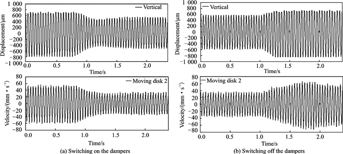
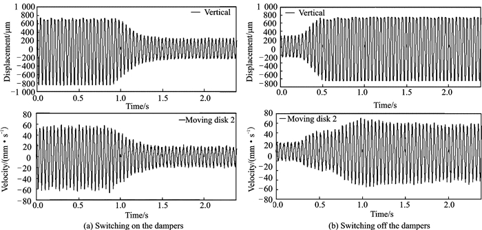
3.1 Time domain response of a rotor with elastic support/dry friction dampers under on-off controlThe time domain responses were tested by a rotor with two active elastic support/dry friction dampers under on-off control. And the parameters of the rotor test rig had been given in Ref.[16]. This type of damper can be controlled by electricity. The two dampers were fixed to each elastic support. The test results are shown in Figs. 6, 7.
|
Fig. 6 Test results of time domain responses of the rotor (Ω =1 407 r/min, U=8 V) |
|
Fig. 7 Test results of time domain responses of the rotor (Ω =1 407 r/min, U=10 V) |
Figs. 6, 7 are the time domain responses of the rotor under on-off control. The control voltages U are 8 V and 10 V. When U = 8 V, the pressing forces between the moving disk and the stationary disk of the two dampers on both ends are 58 N and 70 N, and when U = 10 V, the pressing forces are 87 N and 104 N.
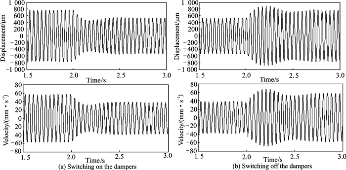
Numerical simulations were carried out by using the parameters of the rotor test rig. In the simulations, the eccentricity ε is 13×10-5 m, the rotation speed Ω is 1 410 r/min, the friction coefficient μ is 0.25, the tangential contact stiffness of the contact interface k is 3×10⁵ N/m, and the pressing forces of two dampers on both ends are 58, 70 N and 87, 104 N. The results are shown in Figs. 8, 9.
|
Fig. 8 Calculation results of time domain responses of the rotor (Ω =1 410 r/min, N1=58 N, N2=70 N) |
|
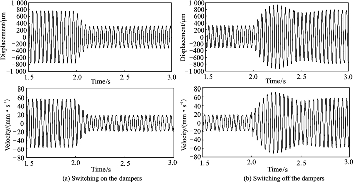
Fig. 9 Calculation results of time domain responses of the rotor (Ω =1 410 r/min, N1=87 N, N2=104 N) |
From Fig. 8(b) and Fig. 9(b), the peak amplitude shows a fluctuation when the damper is switched off. This phenomenon is mainly caused by transient excitation. The transient excitation contains the natural frequency of the rotor system, which leads to a free vibration. Because the natural frequency is close to the rotation speed, it causes a beat vibration. Due to the system damping, the free vibration decays with time and the peak amplitude of rotor is gradually stabilized. What′s more, the larger the damping is, the faster the free vibration decays. So when the damper is switched on, the beat vibration phenomenon is slight in Fig. 8(a) and almost nonexistent in Fig. 9(a).
Comparing each plot in Fig. 8 with Fig. 6 and that in Fig. 9 with Fig. 7, the calculation results show good agreement with the test results. And there are some differences between the experimental damping effect and the calculation results. The main reason is that the pressing force can be affected by the assembly parameters of the damper, which may cause differences in calculation results.
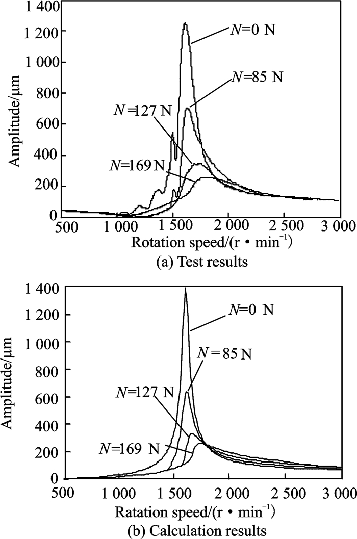
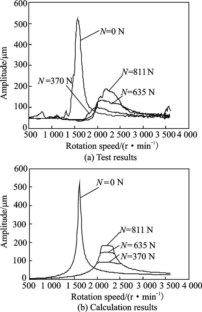
3.2 Amplitude-frequency characteristics of a rotor with elastic support/dry friction dampers under variable pressing forceWith the test rig given in Ref.[12], the amplitude-frequency characteristics of a rotor with elastic support/dry friction dampers under variable pressing force were tested, and two friction pairs were used in the experiments. One was brass/steel and the other was steel/steel. The test results are shown in Fig. 10(a) and Fig. 11(a).Numerical simulations were carried out using the parameters of the rotor test rig. In the simulations, the eccentricities ε are 5.3×10⁻⁵ m and 2×10⁻⁵ m, the friction coefficients μ are 0.19 (brass/steel) and 0.1 (steel/steel), the tangential contact stiffness k of the contact interfaces are 1×10⁶ N/m (brass/steel) and 1×10⁸ N/m (steel/steel), and the rotational speeds are 500-3 000 r/min and 500-4 000 r/min. The results are shown in Fig. 10(b) and Fig. 11(b).
|
Fig. 10 Amplitude-frequency characteristics of the rotor (brass/steel) |
|
Fig. 11 Amplitude-frequency characteristics of the rotor (steel/steel) |
Fig. 10 shows the amplitude-frequency characteristics when the friction pair is brass/steel, and Fig. 11 shows the amplitude-frequency characteristics when the friction pair is steel/steel. The specific values of the peak amplitude in Figs. 10, 11 are shown in Table 1. The difference between the calculation results and the test results is less than 10%. So comparing test results with calculation results in both Fig. 10 and Fig. 11, it is found that the calculation results show good agreement with the test results.
| Table 1 Peak amplitude of the rotor system in test and calculation results |
By the comparisons above, the dynamic model of the rotor with elastic support/dry friction dampers has been verified. The comparisons also show that the variable parameters are very important for the damping performance of the elastic support/dry friction damper. Numerical analysis of some variable parameters will be carried out in the next section.
4 Numerical Analysis 4.1 Basic parameters of the rotorThe geometric dimensions of the rotor for numerical analysis are shown in Fig. 5. The values are as follows: L = 700 mm, a = 250 mm, b = 450 mm, t = 28 mm, r = 120 mm, h =40 mm.
It is assumed that the material of the rotor is steel. Its density ρ is 7.8×10³ kg/m3, and its elastic modulus E is 2.1×10¹¹ N/m2.
Based on the geometric dimensions and material parameters above, the mass, stiffness, moment of inertia, etc., of the rotor can be obtained. In addition, in order to investigate the effect of mode shape on damping effect, mb2 is valued much larger than mb1 to make the vibration amplitude at the right elastic support higher than left on the second mode.
All of the basic parameters are listed in Table 2.
| Table 2 Basic parameters of the rotor for numerical analysis |
4.2 Mode and unbalance response of the rotor
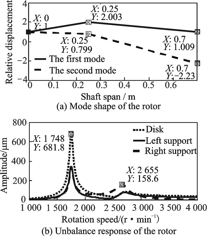
The mode and unbalance response of the rotor can be obtained by solving the homogeneous equations corresponding to Eqs.(3-6) analytically or numerically. The results are shown in Fig. 12, in which Fig. 12(a) is the mode shape of the rotor and Fig. 12(b) is the unbalance response of the rotor.
|
Fig. 12 Mode shape and unbalance response of the rotor |
As shown in Fig. 12, the vibration amplitudes of the left and right supports are approximately equal when the rotor is at the first mode, while at the second mode, the vibration of the rotor is concentrated in the right support.
4.3 Damping performanceIn this section, the damping performance of the elastic support/dry friction damper with respect to variable parameters such as the location of the damper, stiffness of the elastic support, pressing force between the moving and stationary disks, etc., will be discussed with numerical analysis.
4.3.1 Location of the damperThe damping of the elastic support/dry friction damper is caused by the friction between the moving and stationary disks. The moving disk is fixed at the end cross section of the elastic support, so the damping performance of the damper is closely related to the vibration of the elastic support.
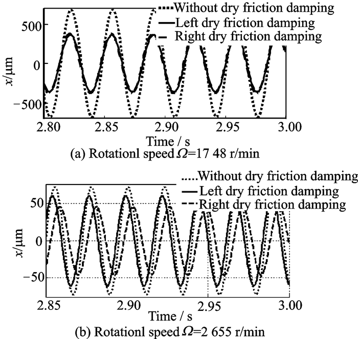
Fig. 12(b) shows that the first and second critical speeds of the rotor are 1 748 and 2 655 r/min, so the numerical analysis of the damper′s performance with respect to the location of the damper was carried out at 1 748 and 2 655 r/min.
Fig. 13 shows the vibration displacement of the rotor disk at 1 748 r/min(Fig. 13(a)) and 2 655 r/min (Fig. 13(b)). In Fig. 13, all three lines represent the vibration of the disk in the rotor system. What makes these lines different is that the dotted line represents the rotor without dry friction damping; the solid line represents the rotor with dry friction damping on the left elastic support (N1 =100 N, N2 =0 N); and the dashed line represents the rotor with dry friction damping on the right elastic support (N1 = 0 N, N2 = 100 N). As shown in Fig. 13(a) and Fig. 13(b), for the first critical speed, the damping performances of the dampers on both elastic supports are almost equal. However, for the second critical speed, the damping performance of the damper on the right elastic support is better than that on the left elastic support.
|
Fig. 13 Damping performance with respect to the location of the damper |
The vibration energy of the rotor system is dissipated by the friction between the friction pairs. At 1 748 r/min, the first mode shape of the rotor in Fig. 12(a) shows that the vibrations of the two supports are almost equal, so in each individual rotation cycle, the vibration energy dissipated by the dampers on the left and right supports is almost the same, which means that the dampers on the two elastic supports show the same damping performance. At 2 655 r/min, the second mode shape of the rotor in Fig. 12(a) shows that the vibration amplitude of the right support is larger than that of the left support, so the vibration energy dissipated by the damper on the right elastic support is larger than that dissipated by the left elastic support, which means that the damper on the right elastic support shows a better performance than the damper on the left elastic support.
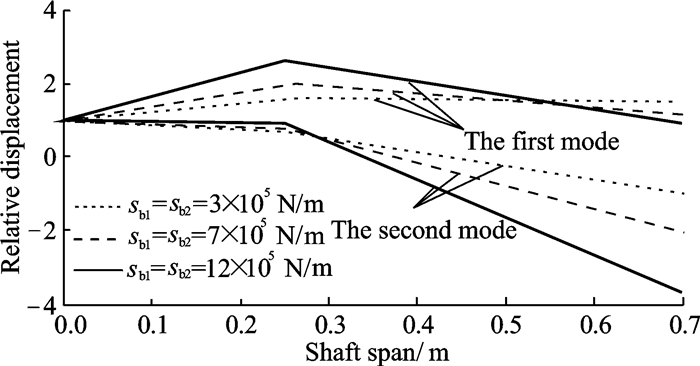
4.3.2 Stiffness of the elastic supportThe critical speed and mode shape can be affected by the elastic support. To study the performance of the elastic support/dry friction damper with respect to the stiffness of the elastic support, let the stiffness of the elastic support be the variable parameters (sb1 = sb2 = 3×10³, 7×10³, and 12×105 N/m). The friction force is applied simultaneously on the left and right elastic supports (N1 = N2 = 20 N).
Fig. 14 is the mode shape of the rotor with the parameters (sb1 = sb2 = 3×10⁵, 7×10⁵, and 12×105 N/m). From Fig. 14, we can see that as the stiffness coefficient of the elastic supports increases, the mode shapes of both the first and second modes become more and more bent, which means that the smaller the stiffness coefficient of the elastic supports, the more vibration energy is concentrated in the elastic support.
|
Fig. 14 Mode shape of the rotor |
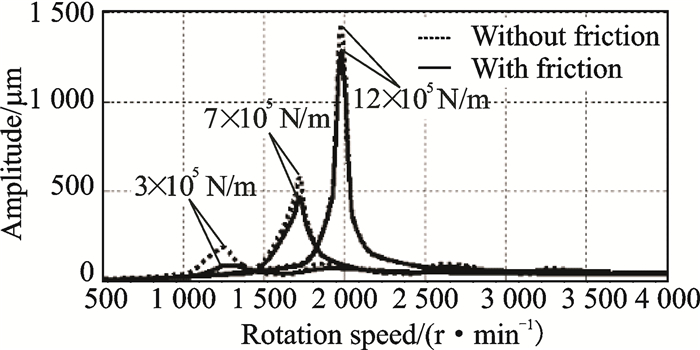
Fig. 15 is the unbalance response of the rotor with the parameters (sb1 = sb2 = 3×10⁵, 7×10⁵, and 12×105 N/m). In this figure, the dotted line represents the response without friction (N1 = N2 = 0 N), and the solid line represents the response with friction (N1 = N2 = 20 N). From the figure, we can see that the damper performance is best when the stiffness coefficient of the support is the smallest, 3×10⁵ N/m; the damper performance is the worst when the stiffness coefficient of the support is the largest, 12×105 N/m.
|
Fig. 15 Unbalance response of the rotor(sb1 = sb2 = 3×10⁵, 7×10⁵, and 12×105 N/m) |
As mentioned above, the smaller the stiffness coefficient of the elastic support, the more vibration energy is concentrated in the elastic support. Additionally, the more vibration energy is concentrated in the elastic support, the more conducive is for the damping performance of the elastic support/dry friction damper. So the damper performs better and better as the stiffness coefficient of the elastic support decreases. For the stiffness coefficient of the elastic support, the operating speed, static deformation, strength and reliability should be taken into consideration.
The above analysis indicates that the damping performance of the elastic support/dry friction damper is closely related to the operating speed of the rotor and the characteristics of the rotor′s mode. Even the same dampers fixed on different rotors or different support locations will perform differently.
4.3.3 Pressing force and friction coefficientThe damping provided by an elastic support/dry friction damper to a rotor is derived from the sliding friction force between the stationary and moving disks. So, as the product of the pressing forces N1 and N2 and the friction coefficient μ, the sliding friction forces μN1 and μN2 directly determine the damping performance of the damper.
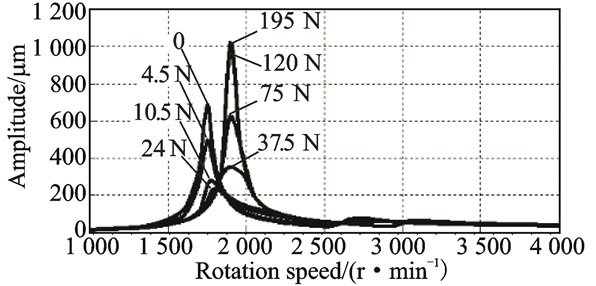
Let the sliding friction forces μN1 and μN2 be the variable parameters, with μN1 = μN2 = 0, 4.5, 10.5, 13.5, 37.5, 75, 120, and 195 N, applied simultaneously. Fig. 17 is the unbalance response of the rotor for the parameter μN1 = μN2 = 0, 4.5, 10.5, 13.5, 37.5, 75, 120, and 195 N.
|
Fig. 16 Unbalance response of the rotor(μN1 = μN2 = 0, 4.5, 10.5, 13.5, 37.5, 75, 120, and 195 N) |
|
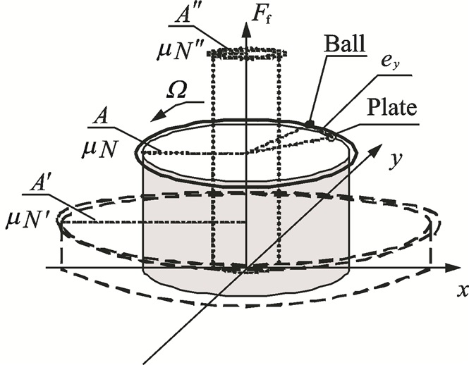
Fig. 17 Hysteresis loops of friction with displacement |
Fig. 16 illustrates the sliding friction forces with μN1 and μN2 increasing. It is found that the critical speed region of the rotor system moves upward, and the peak amplitude of the rotor at the critical speed first decreases and then increases. When the sliding friction forces are large enough, the peak amplitude of the rotor even exceeds the peak amplitude without friction. There must be an optimal sliding friction force under which the unbalance response of the rotor system will be smallest for all rotational speeds, and the rotor can pass through the critical speed smoothly. For this rotor, the optimal sliding friction force is between 24 N and 37.5 N.
This phenomenon can be explained by analyzing the friction hysteresis loops of ball/plate dry friction model in Fig. 17. It shows the relationship between the friction and displacement in a period, where x and y represent the two-dimensional displacement, Ff represents the absolute value of friction whose direction is tangential to the circle. There are two moving trajectories in each period, bigger one is for the ball and smaller one for the plate. Both of them are moving at the rotation speed, and the ball′s phase is ahead of the plate. Their distance ey represents the microscopic sliding. Then, the flank area of the cylinder formed by the plate circle and x-y plane represents the friction work in a period. When the pressure gets smaller, the trajectory of friction goes to the μN′-A′ circle, on the contrary, the trajector y of friction goes to the μN″-A″ circle. Therefore, there is a maximum value of the area when the pressing force changes, also it′s the same for damping effect of damper. Furthermore, the elastic support/dry friction damper not only provides external damping to the rotor system, but also introduces extra stiffness into the rotor system. By calculating the response of the rotor system like Fig. 16, the optimum value can be found.
4.3.4 Stiffness of stationary disk and tangential contact stiffness of contact interfaceBetween the moving disk and the mounting base of the stationary disk, there is a combined stiffness that consists of the stiffness of the stationary disk and the tangential contact stiffness of the contact interface.
(1) The stiffness of the stationary disk
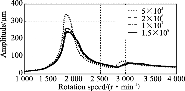
Under the traction of the moving disk, the stationary disk will move slightly. Let the stiffness of the stationary disks sj1 and sj2 be the variable parameters, sj1 = sj2 = 0.05×10⁷, 0.2×10⁷, 1×10⁷, and 15×107 N/m, and the pressing forces of the two dampers, applied simultaneously, be N1 = 150 N and N2 = 150 N.
Fig. 18 is the unbalance response of the rotor with the parameters sj1 = sj2 = 0.05×10⁷, 0.2×10⁷, 1×10⁷, and 15×107 N/m, and N1 = 150 N, N2 = 150 N. The figure shows that as the stiffness coefficient of the stationary disk increases, the peak amplitude of the rotor decreases, while the damping performance of the elastic support/dry friction damper improves. When the stiffness coefficients sj1 and sj2 increase to some extent, the unbalance response curve is nearly constant and the damping performance of the damper no longer changes.
|
Fig. 18 Unbalance response of the rotor (sj1 = sj2 = 5×10⁵, 2×10⁶, 1×10⁷, and 1.5×10⁸ N/m; N1 = 150 N, N2 = 150 N) |
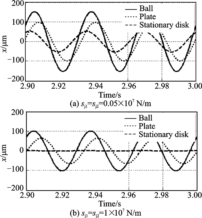
Fig. 19 is the time domain waveform of the left support at 1 800 r/min, with the stiffness coefficients sj1 = sj2 = 0.05×10⁷ N/m and sj1 = sj2 = 1×10⁷ N/m. As shown in Fig. 19(a), when the stiffness coefficient is small, sj1 = sj2 = 0.05×10⁷ N/m, the motion of the stationary disk under the traction of the moving disk is obvious, which makes the relative motion between the moving and stationary disks smaller, so it is unfavourable for the damping performance of the elastic support/dry friction damper. In Fig. 19(b), when the stiffness coefficient is large, sj1 = sj2 = 1×10⁷ N/m, the stationary disk barely moves, which is very favourable for the damper.
|
Fig. 19 Time domain waveform of the left support(Ω =1 800 r/min, N1 = 150 N, N2 = 150 N) |
(2) The tangential contact stiffness of the contact interface
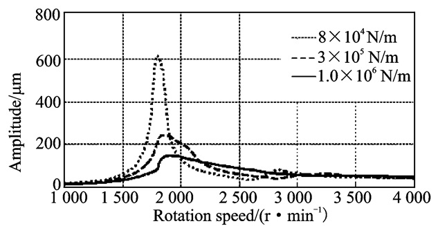
In the ball/plate model (Fig. 4), the tangential contact stiffness of the contact interface is represented by an ideal spring with stiffness coefficient k. Let this stiffness coefficient k be the variable parameter, k = 0.8×10⁵, 3×10⁵, and 10×105 N/m, and the pressing forces of the two dampers, applied simultaneously, N1 = 150 N and N2 = 150 N.
Fig. 20 is the unbalance response of the rotor under the parameter k = 0.8×10⁵, 3×10⁵, and 10×105 N/m, and N1 = 150 N, N2 = 150 N. From Fig. 20, we can see that as the stiffness coefficient k increases, the peak amplitude of the rotor decreases and the damping performance of the elastic support/dry friction damper improves.
|
Fig. 20 Unbalance response of the rotor (k = 8×10⁴, 3×10⁵, and 1.0×10⁶ N/m; N1 = 150 N, N2 = 150 N |
In the ball/plate model (Fig. 4), the plate moves under the traction of the ball. The damping comes from the relative motion between the plate and the stationary disk. When the tangential contact stiffness k is small, the relative motion between the plate and the stationary disk is small, so the damping will be small.
Based on the analysis in this section, it′s clear that the stiffness of the stationary disk sj and the tangential contact stiffness of the contact interface k are connected in series between the moving disk and the mounting base of the stationary disk. The larger this combined stiffness is, the better the damper′s damping performance is.
In addition, the analysis in this paper is mainly based on the circular whirl assumption. In this situation, the trajectory of the moving disk is a circle. So the value of friction does not change with the response of the rotor system in each period, but its direction changes with time. If the circular whirl assumption is invalid, there will be transformation between kinetic and static friction, which may leads to nonlinear phenomenon. Further research is needed in this situation.
5 ConclusionsIn this paper, a two-dimensional friction model-ball/plate model was proposed by which the rotordynamic model of a rotor with elastic support/dry friction dampers was established and experimental verified. Lastly, the damping performance with some variable parameters was studied numerically. The main conclusions are summarized as follows:
(1) A two-dimensional friction model-ball/plate model was proposed. This model is clear and simple, and it can be used to establish the rotordynamic model of a rotor with elastic support/dry friction dampers.
(2) The damping performance of the elastic support/dry friction damper is closely related to the characteristics of the rotor′s mode. To obtain the damper′s best performance, the damper should be located at the elastic support in which the vibration energy is concentrated.
(3) For vibration control, the friction forces should not be maximized, as there is an optimal value at which the elastic support/dry friction damper performs best. The damper not only provides external damping to the rotor system, but also introduces extra stiffness into the rotor system.
(4) The stiffness of the stationary disk and the tangential contact stiffness of the contact interface are connected in series between the moving disk and the mounting base of the stationary disk. The larger this combined stiffness is, the better the damper′s damping performance is.
Acknowledgement
This work was supported by the National Natural Science Foundation of China (No. 51405393).
| [1] |
ABU-MAHHOUZ I, BANERJEE A. On the investigation of nonlinear dynamics of a rotor with rub-impact using numerical analysis and evolutionary algorithms[J]. Procedia Computer Science, 2013, 20(1): 140-147. |
| [2] |
DENG X, LIAO M F, LIEBICH R, et al. Experimental research of bending and torsional vibrations of a double disc rotor due to rotor-to-stator contacts[J]. Journal of Aerospace Power, 2002, 17(2): 205-211. |
| [3] |
OBERST S, LAI J C S, MARBURG S. Guidelines for numerical vibration and acoustic analysis of disc brake squeal using simple models of brake systems[J]. Journal of Sound & Vibration, 2013, 332(9): 2284-2299. |
| [4] |
CIEROLU E, ÖZGVVEN H N. Nonlinear vibration analysis of bladed disks with dry friction dampers[J]. Journal of Sound & Vibration, 2006, 295(3): 1028-1043. |
| [5] |
GRIFFIN J H, MENQ C H. Friction damping of circular motion and its implications to vibration control[J]. Journal of Vibration and Acoustics, 1991, 113(2): 225-229. DOI:10.1115/1.2930173 |
| [6] |
QI W K, ZHANG Y J. Reduced vibration characteristics of turbine blade with platform damper[J]. Joernal of Nanjing University of Aeronautics & Astronautics, 2014, 46(2): 280-284. |
| [7] |
HE B B, OUYANG H J, REN X M, et al. Dynamic response of a simplified turbine blade model with under-platform dry friction dampers considering normal load variation[J]. Applied Sciences, 2017, 7(3): 228. DOI:10.3390/app7030228 |
| [8] |
DING Q, CHEN Y. Analyzing resonant response of a system with dry friction damper using an analytical method[J]. Journal of Vibration & Control, 2008, 14(8): 1111-1123. |
| [9] |
WANG L Q, LI W Z, GU L, et al. Reducing vibration with friction-damping in high-speed rotor system[J]. Transactions of Nanjing University of Aeronautics & Astronautics, 2007, 24(1): 48-53. |
| [10] |
XING J, HE L D, WANG K. Optimizing control for rotor vibration with magnetorheological fluid damper[J]. Transactions of Nanjing University of Aeronautics & Astronautics, 2014, 31(5): 538-545. |
| [11] |
FAN T Y, LIAO M F. Dynamic behavior of a rotor with dry friction dampers[J]. Mechanical Science and Technology, 2003, 22(5): 743-745. |
| [12] |
FAN T Y. Vibration reduction by elastic support dry friction damper[D]. Xi'an: Northwestern Polytechnical University, 2006. (in Chinese)
|
| [13] |
WANG S J, LIAO M F, YANG S J. Experimental investigation on vibration control by elastic support/dry friction damper[J]. Journal of Aerospace Power, 2007, 22(11): 1893-1897. |
| [14] |
WANG S J, LIAO M F. Experimental investigation of an active elastic support/dry friction damper on vibration control of rotor systems[J]. International Journal of Turbo & Jet Engines, 2014, 31(1): 13-17. |
| [15] |
WANG S J, LIAO M F. Control strategy and methods of rotor systems by an elastic support/dry friction damper[J]. Journal of Aerospace Power, 2011, 26(10): 2014-2219. |
| [16] |
WANG S J. Vibration control techniques for rotor systems by an active elastic support/dry friction damper[D]. Xi'an: Northwestern Polytechnical University, 2008. (in Chinese)
|
| [17] |
WANG S J, LIAO M F. Online Control of rotor system instability by elastic support/dry friction damper[J]. Journal of Vibration Measurement & Diagnosis, 2012, 32(2): 323-327. |
| [18] |
WANG S J, LIAO M F. Application of an active elastic support/dry friction damper to control sudden unbalance response of rotor systems[J]. Mechanical Science and Technology, 2008, 27(5): 667-672. |
| [19] |
LIAO M F, SONG M B, WANG S J. Active elastic support/dry friction damper with piezoelectric ceramic actuator[J]. Shock and Vibration, 2014, 2014(2): 1-10. |
| [20] |
SONG M B. Dynamic design of elastic support/dry friction damper matching rotor[D]. Xi'an: Northwestern Polytechnical University, 2016. (in Chinese)
|
| [21] |
WANG S J, LIAO M F. Protection of a rotor against violent vibrations caused by a crack in elastic supports by using active elastic support/dry friction dampers[J]. Journal of Aerospace Power, 2008, 23(11): 2026-2030. |
 2018, Vol. 35


