Helicopters, which have the advantages of vertical flight, hovering operation, low-altitude maneuverability capabilities and so on, have been widely used all around the world. However, when helicopters fly across the city, especially in landing condition, radiated noise from helicopters has serious impact on surroundings and population[1], which is the limit factor of further usage of helicopters. On the one hand, in order to restrict the civil helicopter noise, international civil aviation organization (ICAO) has issued stringent airworthiness regulations of helicopter noise, and the noise control standards will become more stringent in the future. On the other hand, to improve the acoustic stealth performance of military helicopters, tactical and technical criteria often contain some low-noise requirements. So far, helicopter noise reduction has been a research hotspot and gradually become an important research direction in the field of helicopter technology[2].
Rotor is the dominant external noise source of a helicopter, so it is also the important research object of helicopter noise reduction. According to previous researches, the aerodynamic design of rotor blade, especially blade tip, is an effective method to reduce the rotor noise[3]. Anhedral tip is one important type of three-dimensional blade tip, which has been successfully applied to several advanced helicopter rotor designs, such as the rotor of UH-60M and AW-101 helicopters. So far, several new type blade tips[4-5] have been designed and analyzed, however, as for anhedral tips, the research is almost focused on the rotor aerodynamic performance. Mantay et al.[6] comprehensively analyzed the effect of back-sweep and tapered blade tip on the rotor aerodynamic performance, and in this work, blade tips with anhedral angle are tested for the first time. Anhedral blade tip was also studied for the S-76 rotor enhancement by Balch[7], whose emphasis was aimed at achieving good figure of merit(FM). Muller et al.[8-9] investigated the aerodynamic performance of the rotor with anhedral blade tip, and the result also showed that the rotor hover performance could be improved by the usage of anhedral blade tip. Guo et al.[10] carried out some studies on the aerodynamics/aeroacoustic optimization of blade tip planform for helicopter rotor. Zhao and Xu conducted some researches on the rotor aerodynamic layout design, in which a new blade-tip named after "CLOR"[11-12] was designed, analyzed and tested. Although many of analytical and experimental studies on the rotor aerodynamic performance with anhedral blade tip have been conducted, there is still limited research focused on the aeroacoustic characteristics of anhedral blade tip, especially by the means of both analytical and experimental methods. Meanwhile, there is lack of reliable experimental data for numerical calculation models. For these reasons, an experiment on the model rotors with anhedral blade tip is conducted, and the influence of anhedral blade tip on the rotor aerodynamic and aeroacoustic characteristics in hover is analyzed.
The model rotors with different tip anhedral angles are manufactured with composite material, and experimental investigations on the effects of blade-tip anhedral angle on the aerodynamic performance and aeroacoustic characteristics in hover are conducted in the anechoic chamber. Meanwhile, to further analyze the influence mechanism of the anhedral blade tip, the pressure distribution of different blade sections and blade-tip vortex spatial distribution are simulated by means of computational fluid dynamics (CFD). Then, some conclusions are obtained, which can be used in the aerodynamic design of advanced rotor.
1 Experiment 1.1 Experiment model and basic parametersIn the experiment, three model rotors are manufactured with glass fiber composite material. Through structure design and dynamic optimization, the model rotors have reasonable dynamic characteristics and enough structural strength to avoid damage of rotor blades and experiment stand due to serious vibration. The configuration of the model rotor blades are parabolic sweepback, with different blade tip anhedral angle 0°, 20° and 45°. The basic parameters of model rotors are shown in Table 1. The schematic of the rotors is shown in Fig. 1.
| Table 1 Basic parameters of the model rotor |

|
Fig. 1 Schematic of the blade tip with different anhedral angels |
1.2 Experiment environment and apparatus
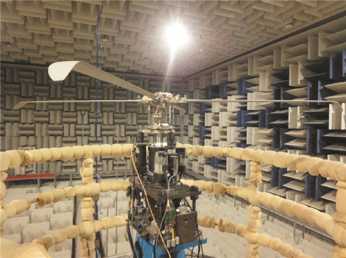
The experiment is carried out in the acoustic chamber of CHRDI. The inner four sides of the acoustic chamber are covered with anechoic wedges, forming an anechoic experimental surrounding with a cut-off frequency of 60Hz. The inverse flow installation is arranged below the rotor stand to avoid the rotor inverse flow effects. In addition, the fence of the rotor stand is wrapped with acoustic foams, which can decrease the interaction influence of stand fence on rotor noise transmission.Fig. 2 shows the test environment and experiment rig.
|
Fig. 2 Test environment and experiment stand |
The microphones used are BSWA′s MPA201, 1/2 inch, ICP type. The basic parameters of the microphones are shown in Table 2.
| Table 2 Basic parameters of the microphone |
To avoid the influence of the rotor induced flow on the noise measuring, the nose cones are installed on the microphones.
The MF10SN type collector produced by German Mueller-BBM company is used as the data acquisition and processing system, which includes 48 IEPE type signal channels of vibration and noise. Signals are collected synchronously in each channel, and the highest sampling rate is up to 200KHz/S/CH. The data acquisition and processing system also has functions of processing sound pressure, sound pressure level, sound intensity, sound power and sound power level and other data.
In this experiment, the time history of rotor aerodynamic noise is directly measured by the microphones, and in each rotor test status, 10 s of sound pressure data was recorded. However, because of random signals existing in the original data, a further data processing is needed. Therefore, in this experiment, noise signals of approximately 60 rotor rotation periods are chosen to be averaged in time, and then these averaged noise signals are used as the time history of sound pressure, as shown in Fig. 3.

|
Fig. 3 Averaged time history of rotor acoustic pressure |
1.3 Layout of microphone location
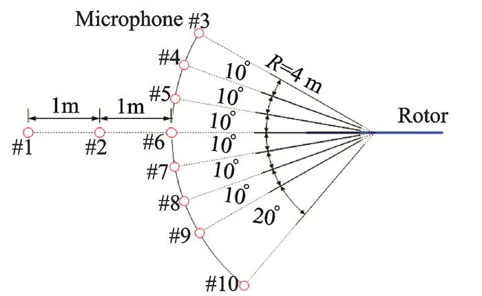
The rotor flowfields in hover can be supposed to quasi-steady flows, therefore, the radiating sphere of rotor noise can be simplified to a circle arc in two dimensions. The microphone position is grouped into: (1) circle arc microphones (4m radius from the rotor hub center, numbered #3~#10), that are applied to measure the acoustic characteristics of positions with different angles to the rotor plane; (2) in rotor disk plane microphone, that are used to measure acoustic characteristics of positions with different distances to the rotor hub center (#1:6m, #2:5m). The microphone layout is shown in Fig. 4.
|
Fig. 4 Schematic of the positions of microphones |
1.4 Test method
The rotor speed of rotation is 2 064 rev/min in the present experiment, the aerodynamic force and acoustic data of the model rotors with different anhedral angles are measured in hover. The number of rotor blade is set to two and four. The experiment is conducted by scanning the blade pitch, covering 2°—10°. The rotor thrust and the torque are measured by the rotor balance. Moreover, the rotor noise time history of the different observation positions are measured by the microphones. When measuring the rotor noise, six times of data are recorded in each rotor operating status, while recording 15s noise signal each time.
2 CFD Analysis Method for Rotor Flowfiled SimulationTo analyze the influence mechanism of the anhedral blade tip on the flow-filed and aerodynamic characteristics of rotor, the CFD technique[13] has been introduced to simulate the flow-field of rotor.
| $ \frac{\partial }{\partial t}\iiint\limits_{\partial V}{\mathit{\boldsymbol{W}}dV}+\iint\limits_{\partial S}{\left[F\left( \mathit{\boldsymbol{W}} \right)-G\left( \mathit{\boldsymbol{W}} \right) \right]\text{d}S}=\iiint\limits_{\partial V}{\mathit{\boldsymbol{Q}}\text{d}V} $ | (1) |
The expressions of conservation variables W, convection fluxes F, viscous fluxes G and source terms Q are
| $ \mathit{\boldsymbol{W}} = \left[\begin{array}{l} \rho \\ \rho u\\ \rho v\\ \rho w\\ \rho E \end{array} \right], {\rm{ }}\mathit{\boldsymbol{F}} = \left[\begin{array}{l} \rho ({q_n}-{q_b})\\ \rho u({q_n}-{q_b}) + p\mathord{\buildrel{\lower3pt\hbox{$\scriptscriptstyle\frown$}} \over n} {_x}\\ \rho v({q_n}-{q_b}) + p{{\mathord{\buildrel{\lower3pt\hbox{$\scriptscriptstyle\frown$}} \over n} }_y}\\ \rho w({q_n} - {q_b}) + p{{\mathord{\buildrel{\lower3pt\hbox{$\scriptscriptstyle\frown$}} \over n} }_z}\\ \rho H({q_n} - {q_b}) + p{q_b} \end{array} \right] $ |
| $ \mathit{\boldsymbol{G}} = \left[\begin{array}{l} 0\\ {\tau _{xx}}{{\mathord{\buildrel{\lower3pt\hbox{$\scriptscriptstyle\frown$}} \over n} }_x} + {\tau _{yx}}{{\mathord{\buildrel{\lower3pt\hbox{$\scriptscriptstyle\frown$}} \over n} }_y} + {\tau _{zx}}{{\mathord{\buildrel{\lower3pt\hbox{$\scriptscriptstyle\frown$}} \over n} }_z}\\ {\tau _{xy}}{{\mathord{\buildrel{\lower3pt\hbox{$\scriptscriptstyle\frown$}} \over n} }_x} + {\tau _{yy}}{{\mathord{\buildrel{\lower3pt\hbox{$\scriptscriptstyle\frown$}} \over n} }_y} + {\tau _{zy}}{{\mathord{\buildrel{\lower3pt\hbox{$\scriptscriptstyle\frown$}} \over n} }_z}\\ {\tau _{xz}}{{\mathord{\buildrel{\lower3pt\hbox{$\scriptscriptstyle\frown$}} \over n} }_x} + {\tau _{yz}}{{\mathord{\buildrel{\lower3pt\hbox{$\scriptscriptstyle\frown$}} \over n} }_y} + {\tau _{zz}}{{\mathord{\buildrel{\lower3pt\hbox{$\scriptscriptstyle\frown$}} \over n} }_z}\\ {\mathit{\Phi} _x}{{\mathord{\buildrel{\lower3pt\hbox{$\scriptscriptstyle\frown$}} \over n} }_x} + {\mathit{\Phi} _y}{{\mathord{\buildrel{\lower3pt\hbox{$\scriptscriptstyle\frown$}} \over n} }_y} + {\mathit{\Phi} _z}{{\mathord{\buildrel{\lower3pt\hbox{$\scriptscriptstyle\frown$}} \over n} }_z} \end{array} \right], {\rm{ }}\mathit{\boldsymbol{Q}}{\rm{ }} = \left[\begin{array}{l} 0\\ \rho w\mathit{\Omega} \\ 0\\ -\rho u\mathit{\Omega} \\ 0 \end{array} \right] $ |
In the formulas, ρ, u, v, w and p denote the fluid density, velocity in three directions and pressure, respectively. E and H are internal energy and enthalpy per unit mass.
Ω is the angular velocity of rotation, τ is the viscous stress. [nx ny nz]T are the normal vector.
In CFD solver, a second-order upwind scheme(Roe scheme)[14] is used to calculate the convective fluxes on the faces of the control volume. For the time integration, the dual-time stepping method is applied to simulate the unsteady flow phenomenon, and the LU-SGS scheme[15] is employed in every pseudo-time step. In addition, the Spalart-Allmaras one equation model[16] is used as the turbulence model, which is uncoupled with the flow governing equations.
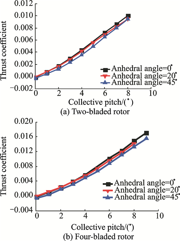
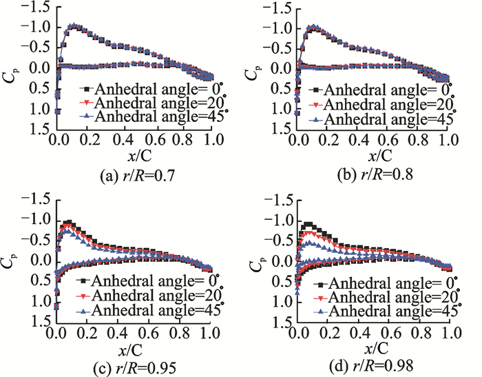
3 Experiment Results and Analysis 3.1 Results of hover performance and analysisFig. 5 shows the variation of thrust coefficient of different blade tip anhedral angles with collective pitch under two-bladed and four-bladed conditions. It shows that with the same collective pitch, the anhedral blade tip will decrease the rotor total thrust. To analyze the influence of anhedral angle on the rotor thrust comprehensively, the pressure distribution of different blade sections is calculated by using the CFD code, as shown in Fig. 6. It can be seen that, the anhedral blade tip will decrease the airloads of blade outboard portion, but has little influence on the airloads of blade inboard portion, which will result in the decrease of the total rotor thrust. The decrease of airloads of blade outboard portion is beneficial to improving the characteristics of aerodynamics and aeroacoustics.
|
Fig. 5 Comparison of rotor thrust with different blade-tip anhedral angles |
|
Fig. 6 Comparison of blade section pressure coefficients among rotors with different blade-tip anhedral angles |
Fig. 7 presents the hover performance curves of the rotor with different blade tip anheral angles under five-bladed and four-bladed conditions. It can be seen that, the anhedral blade tip can effectively enhance FM of the rotor with the maximum increment of five percent in the experiment. In addition, Fig. 7 also shows that there is no obvious difference between the blade tip anhedral angle 20°and 45°. And in the four-bladed rotor experiment, the maximum FM of the rotor with blade tip anhedral angle 45° is smaller than that of rotor with blade tip anhedral angle 20°, and it′s also indicated that FM of the rotor will not always increase with the increase of blade tip anhedral angle.

|
Fig. 7 Comparison of figure of merit among rotors with different blade-tip anhedral angles |
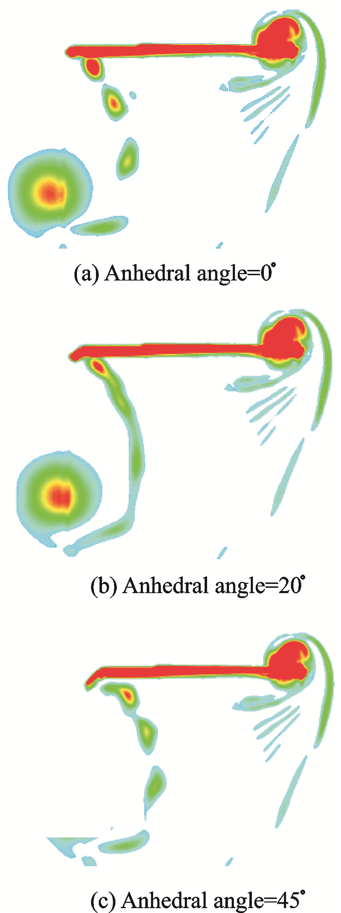
To further analyze the influence mechanism of blade tip anhedral angle on the hover performance of the rotor, the vortex flowfield of the rotor is simulated by using the CFD code, as shown in Fig. 8. It can be seen that, the anhedral blade tip can increase the distance between the rotor wake and the rotation plane, and decrease the vortex strength of the rotor wake, which will decrease the rotor induced power and enhance FM of the rotor consequently. It also should be noted that the increase of the distance between rotor wake and rotation plane is beneficial to weakening the blade-vortex interaction phenomenon.
|
Fig. 8 Comparison of vortex flow-filed simulated by CFD method among rotors with different blade-tip anhedral angles |
3.2 Test results of noise in hover
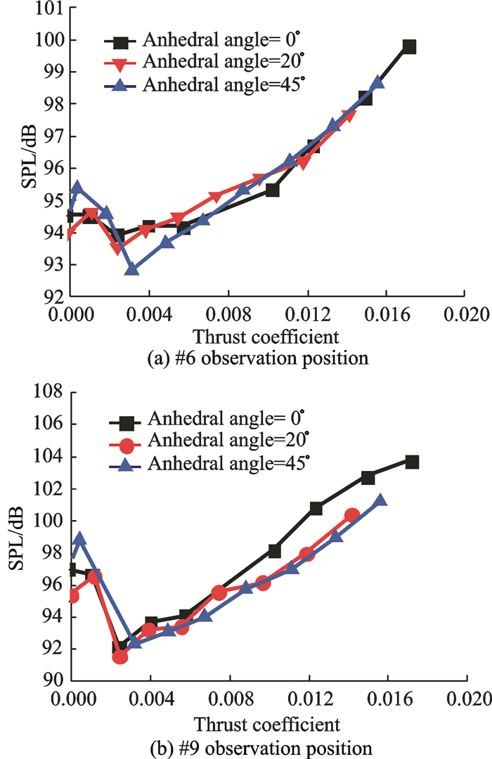
Fig. 9 shows the variation of the measured sound pressure level (SPL) with thrust coefficient of the rotors with different blade tip anhedral angles at the #6 observation point in the rotor disk plane and #9 observation point 30 degrees below the rotor disk. In this figure, the tested rotor is four-bladed. It can be seen that the anhedral blade tip has little influence on the aeroacoustics of #6 position. However, the decrease of the acoustic level occurs at #9 microphone below the rotor. And, the noise reduction effects with anhedral angles 20° and 45° are almost the same. Previous studies indicate that the rotor aerodynamic noise is dominated by the thickness noise in the rotor disk plane, while the load noise is dominant below the rotor disk plane. It can be inferred that the anhedral blade tip has little influence on the rotor thickness noise, but has some effect on the rotor load noise reduction to some degree.
|
Fig. 9 Comparison of SPL among four-bladed rotors with different blade-tip anhedral angles |
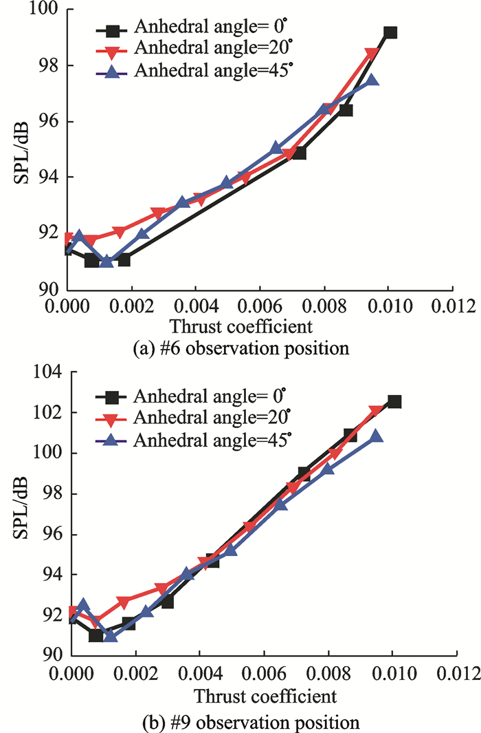
Fig. 10 shows the acoustic results with two-bladed rotor. It can be seen that, similar acoustic results are obtained from the rotors with two and four blades. However, the noise reduction effect of two-bladed rotor is not as good as the four-bladed one. Meanwhile, the acoustic level of two-bladed rotor with anhedral blade-tip increases a little in the disk plane of rotor.
|
Fig. 10 Comparison of SPL among two-bladed rotors with different blade-tip anhedral angles |
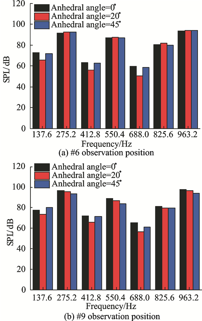
Fig. 11 shows the comparison of frequency spectrum of the rotors with different anhedral blade tips. It indicates that, at #6 observation point, the sound pressure level of each noise harmonic is almost the same for the rotors with different anhedral blade tips. However, at #9 observation point, the sound pressure level of each noise harmonic of the rotor with anhedral blade tip is lower than that of the rotor without anhedral blade tip. Moreover, the frequency spectrum result of rotor acoustics is consistent with the results of overall sound pressure level.
|
Fig. 11 Comparison of noise frequency spectrum among four-bladed rotors with different blade-tip anhedral angles |
4 Conclusions
An experiment and analysis on aerodynamic performance and aeroacoustics characteristics of the rotors with different blade tip anhedral angles in hover are conducted in this paper, the following conclusions can be drawn.
(1) Under the present experimental condition, the anhedral blade tip will result in the decrease of the rotor thrust in hover, especially the airloads of the blade outboard portion.
(2) The anhedral blade tip will make the rotor tip vortex far from the rotor disk plane. Meanwhile, the strength of blade tip vortex will be also reduced. Consequently, the figure of merit of the rotor with anhedral blade tip increases.
(3) The anhedral blade tip has little influence on the rotor thickness noise, but has some effects on the rotor load noise which can be reduced to some extent.
(4) Under the conditions of the present experiment, for the two-bladed and four-bladed rotors, blade tip anhedral angle 20°and 45° have similar effect on the rotor aerodynamic performance and aeroacoustics in hover. However, anhedral angle 20° may be more suitable for blade design in consideration of the difficulty of blade structural design and dynamic optimization.
| [1] |
ALLONGUE M, MARZE H J, POTDEVIN F. The quiet helicopter—From research to reality[C]//The American Helicopter Society 55th Annual Forum. Montreal, Canada: AHS International, Inc. 1999: 1-17.
|
| [2] |
BRENTNER K S. Prediction of the helicopter rotor discrete frequency noise—A computer program incorporating realistic motions and advanced acoustic formulation: NASA-TM-87721[R]. USA: NASA, 1986.
|
| [3] |
BROCKLEHURST A, BARAKOS G N. A reviewer of helicopter rotor blade tip shapes[J]. Progress in Aerospace Science, 2013, 56: 35-74. DOI:10.1016/j.paerosci.2012.06.003 |
| [4] |
HARRISON R, STACEY S, HANSFORD B. BERP IV-The design, development and testing of an advanced rotor blade[C]//The American Helicopter Society 64th Annual Forum. Montreal, Canada: AHS International, InC. 2008: 1-20.
|
| [5] |
PRIEUR J, SPLETTSTOESSER W R. ERATO: An ONERA-DLR cooperative programme on aeroacoustic rotor optimization[C]//The 25th European Rotorcraft Forum. Rome, Italy: ERF International, InC. 1999: 1-13.
|
| [6] |
MANTAY W R, YEAGER J W T. Parametric tip effects for conformable rotor applications: NASA-TM-85682[R]. USA: NASA, 1983.
|
| [7] |
BALCH D T. Experimental study of main rotor/tail rotor/airframe interaction in hover[J]. Journal of the American Helicoper Society, 1985, 30(2): 49-56. DOI:10.4050/JAHS.30.49 |
| [8] |
MULLER R H G, STAUFENBIEL R. The influence of winglets on rotor aerodynamics[J]. Vertica, 1987, 11(4): 601-618. |
| [9] |
MULLER R H G. Special vortices at a helicopter rotor blade[J]. Journal of the American Helicopter Society, 1990, 35(4): 16-22. DOI:10.4050/JAHS.35.16 |
| [10] |
GUO W L, SONG W P, XU J H, et al. An effective aerodynamics/acoustic optimization of blade tip planform for helicopter rotors[J]. Journal of Northwestern Polytechnical University, 2012, 30(1): 73-79. |
| [11] |
ZHAO Q J, XU G H. Aerodynamic performance of rotor with new type blade-tip in hover based upon test and numerical investigations[J]. Acta Aeronautic et Astronautica Sinica, 2009, 30(3): 422-429. |
| [12] |
WANG B, ZHAO Q J, FAN F, et al. Investigations on acoustic characteristics of rotor with improved CLOR blade-tip in hover based on experimental and prediction method[J]. Acta Aerodynamic Sinica, 2013, 31(4): 454-461. |
| [13] |
FAN F, SHI Y J, XU G H. Computational research on aerodynamic and aeroacoustic characteristics of scissors tail-rotor in hover[J]. Acta Aeronautica et Astronautica Sinica, 2013, 34(9): 2100-2109. |
| [14] |
ROE P L. Approximate Riemann solvers, parameter vectors, and difference schemes[J]. Journal of Computational Physics, 1981, 43(2): 357-372. DOI:10.1016/0021-9991(81)90128-5 |
| [15] |
LUO H, BAUM J D. A fast matrix-free implicit method for computing low mach number flows on unstructured grids: AIAA 99-3315[R]. USA: AIAA, 1999.
|
| [16] |
SPALART P R, ALLMARAS S R. A one-equation turbulence model for aerodynamic flows: AIAA 92-0439[R]. USA: AIAA, 1992.
|
 2018, Vol. 35


